Channel Scaling

Scaling a Channel using configuration software

Purpose

This guide reviews how to connect a channel to a Q.series module and scale the channel to engineering units.


Requirements

  • The controller has already been configured using GI.bench/test.commander
  • Measured module attached with input channels
  • Sensor

If needing to perform more than 2 points of linearization, it is possible to create a custom sensor and input the points of linearization. The sensor will extrapolate from the curve. See this article for more infomation.

Procedure (GI.bench)

  1. Open existing project or click Read under the Configuration tab to load project
  2. Double-click on the channel that needs to be configured
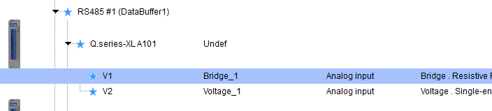
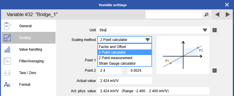
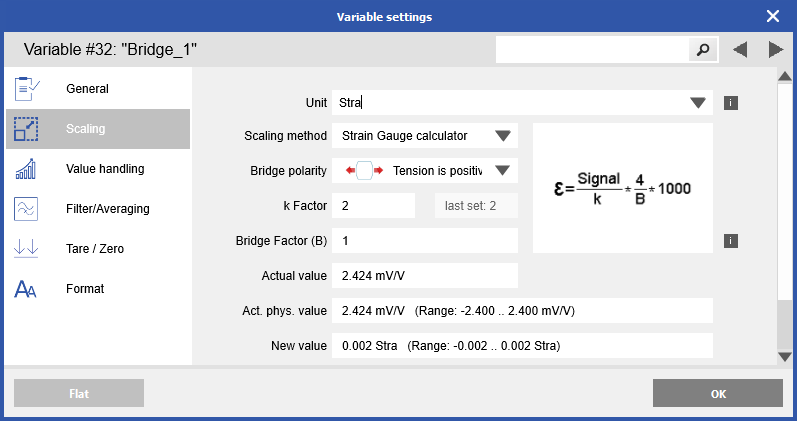
  3. In the variable settings window navigate to the Scaling section. Select desired units from drop-down list or type in custom unit name
  4. Under the Scaling method there is Factor and Offset, 2 point calculator, 2 point measurement (if live acquistion activated), and strain gauge calculator (if bridge input).

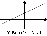
    1. Factor and Offset: Y = Factor * X + Offset
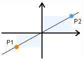
    2. 2 Point calculator: With the 2-point calibration (for linear sensors), the points for calibration can be defined here from the “physical” measurement value to the “engineering” value. The following picture shows the situation of these points:
    3. 2 Point measurement: see article
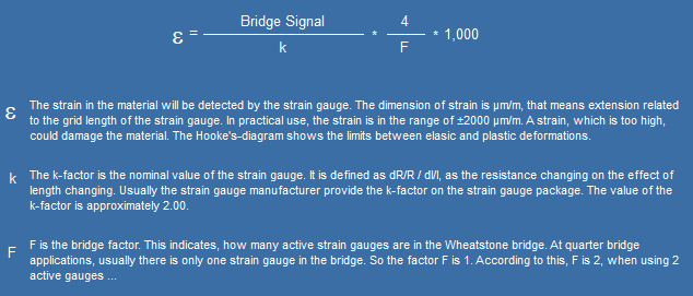
    4. Strain Gauge calculator: enter bridge settings such as bridge polarity (which direction is positive/negative), k and bridge factor, and unit
  5. Make sure to write any changes to the DAQ system

Procedure (test.commander)

  1. Double-click on the channel that needs to be configured. In this example, we will use the channel below-called Tweezers, on an A101 module.


  2. The module will open in ICP 100:


  3. For this example, we are concerned with V2.

  4. Double-click on the cell under Variable Name to change the channel's name. Click OK to confirm.


  5. Double-click on the cell under Sensor to change the sensor. Select the sensor and click OK to confirm. We will be using a Bridge for this example.


  6. There are more options available for each sensor. Double-click on the cell under Type of to select the specific sensor type. We have a full 4-wire bridge for this example.


  7. Based on the sensor type and location of the channel in the project, the Connection and
    Terminals column will display how to wire the sensor (which connector and which pins).


  8. At this point, we recommend wiring the sensor you are using to the measurement module.

  9. Depending on the module being used and the type of sensor, ICP 100 will already display the default unit to be used. For this example, since we use a bridge input, the sensor uses mV/V as our suggested unit.


  10. Double-click on the cell under the Format/Adjustment column. The following window will appear. The option to use the default unit is possible, but to scale to engineering units, manually enter the desired unit and click the Scaling button. We will use lbs. for this example.


  11. The unit conversion window appears.
    1. Under Input value is the raw signal the module is reading. (±2.4 mV/V is being shown as ±0.0024 V/V). Point 1 is the low end of the range, and Point 2 is the high end of the range.
    2. Under the Engineering value is the desired units to be displayed and saved. For this example, ±2.4 mV/V will correspond to ±500 lbs.
    3. Click OK to confirm settings.


  12. Click OK on the Unit and Format window.

  13. Save the settings in ICP 100.

  14. Update the project to the controller.

  15. Notice that the channel is now displaying in Engineering Units of lbs.