End-to-End Calibration using Live Measurement Data

Physical end-to-end calibration and adjustment ensures accurate data collection by thoroughly inspecting the measurement system components, allowing for early detection and correction of potential issues.

Calibration procedure in GI.bench

  1. To load the configuration of the connected DAQ system into the project window, click Read or open an existing project that matches the connected hardware configuration.

  2. Next, navigate to the Data Acquisition tab to initiate the acquisition process.

  3. You can either right-click and select Edit variable from either the data acquisition or configuration tab to access the variable settings window.

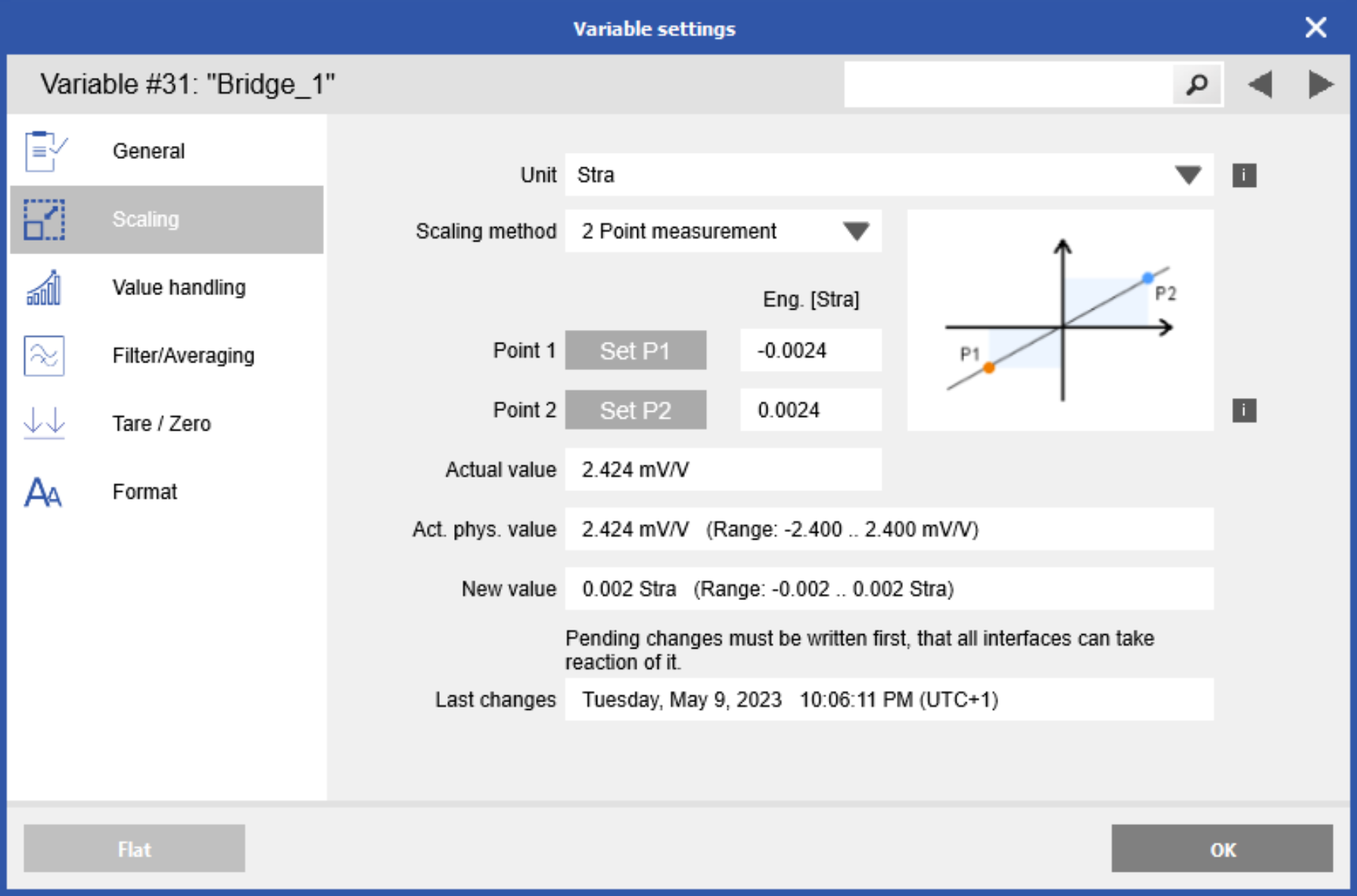
  4. From there, you can choose or input the desired engineering unit for scaling purposes.

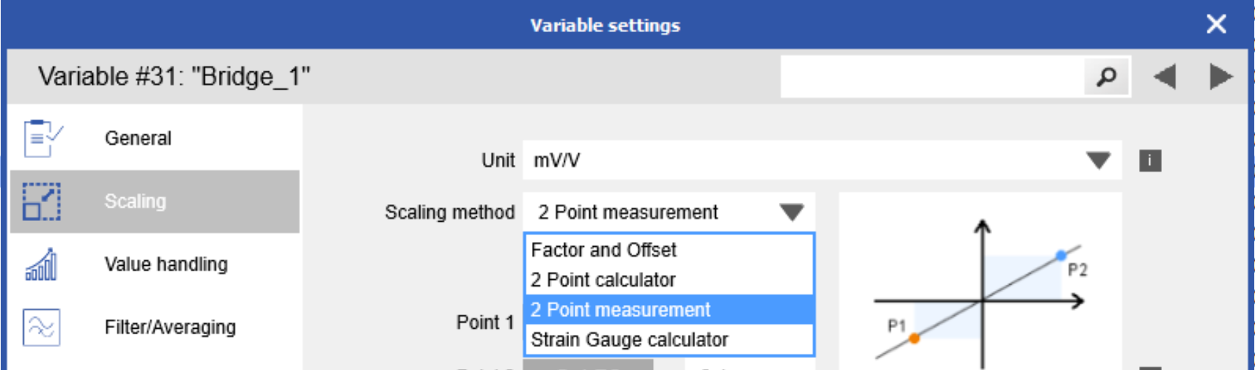
  5. In the scaling section, you'll find a drop-down list for the scaling method, which now includes the option for 2 Point Measurement. 

  6. Assign a value to the signal and then click Set P1. Proceed by applying the next value and clicking Set P2. This process establishes a two-point scaling relationship between the physical and engineering units. All data points will be linearized according to this established line.

  7. Click OK when complete, then go to Configuration > Write to write updates to the DAQ system.

Calibration procedure in test.commander

  1. Connect the controller and add it to the current project. The controller and all I/O modules should be shown in the project space:


  2. Highlight the attached controller and select Online adjust values from the controller:


  3. The online adjustment window will appear.

  4. Click on the variable you want to calibrate and select the Adjustment button to the right:


  5. Select the 2-point calibration by measure:


  6. For this example, we have a signal generator connected to an A101 for voltage input 0-10V. For demonstration purposes, we will set Point 1 to -10V (with an actual input of 0V) and set Point 2 to 10V (with an actual input of 10V). With this calibration, an actual input of 5V will be displayed as 0V.

  7. Set the signal generator to 0V, ensure Point 1 displays -10V, and click Set value.

  8. Set the signal generator to 10V, make sure Point 2 displays 10V, and click Set value.

  9. Click OK when complete.

  10. You will notice that when the signal generator is set to 0V, the A101 will display -10V; when set to 10V, the A101 will display +10V. All values in between these two points are linearized:

    Signal Generator A101
    0V -10V
    2V -6V
    4V -2V
    5V 0V
    8V 6V
    10V 10V

     
    Example: (signal generator set to 8V)


  11. Make sure to update the project to the connected test controller.