Synchronizing a Controller with an External Time Source
Overview of supported time synchronization protocols and setup instructions
Overview
Synchronizing the clocks of networked devices is essential to ensure measurement data aligns across all systems. Several methods exist to synchronize controllers to an external clock, each with its own advantages. The following sections describe the protocols supported by the Q.series controllers.
Time protocols
|
Type |
Accuracy |
Distance |
Medium |
Recommended for |
|
GPS |
< 1 s |
- |
USB, RS-232 |
Long-distance and mobile measurement applications |
|
< 10 ms (local) |
100 m |
Ethernet |
Low-speed, distributed measurement systems |
|
|
PTPv2 |
< 100 ns |
1 km |
Ethernet |
High-speed, networked measurement systems |
|
< 100 ns |
50 m |
TTL, RS-485 |
Installations with existing IRIG-B signal generator |
|
|
AFNOR |
< 100 ns |
50 m |
TTL, RS-485 |
Installations with existing AFNOR signal generator |
|
EtherCAT DC |
< 100 ns |
100 m |
Ethernet |
High-precision measurement and control application |
Depending on the controller type, up to 3 different time sources can be configured. Depending on availability, the most accurate time source will be selected. The accuracy of the signals is according to this order:
-
PTPv2/IRIG/AFNOR
- NTP
- GPS NMEA 0183
The Q.monixx controller supports time synchronization via NTP and GPS only.
GPS NMEA 0183
GPS receivers communicate using several protocols. Of all message standards that are used with GPS receivers, the NMEA 0183 is the most widely used messaging standard. NMEA is the acronym for the National Marine Electronics Association.
The controller supports the following NMEA sentence codes:
-
$GPRMC (Recommended minimum specific GPS/Transit data)
-
$GPGGA (Global Positioning System Fix Data)
For more information about setting up NMEA 0183 synchronization see: How to bring GPS signals into a controller.
The NMEA 0183 sentences are not synchronized to be generated at specific intervals. These GPS receivers therefore can only provide an accuracy of plus or minus 1 second.
NTP

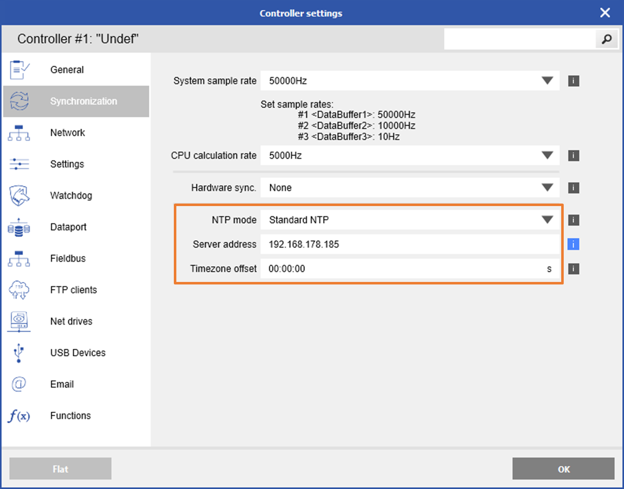
The controller is configured to synchronize with an NTP server at approx. 1 Hz, which can generate up to ~9 MB of data traffic per day. When using an internet-based NTP server, this may result in additional charges depending on your cellular data plan.
PTPv2
PTP stands for Precision Time Protocol and is a time synchronization protocol for nodes distributed across a network. Its hardware timestamp feature provides greater accuracy than other time synchronization protocols such as NTP.
PTP is a distributed protocol that specifies how real-time PTP clocks in the system synchronize with each other. These clocks are organized into a master-slave synchronization hierarchy with the grandmaster clock, which is the clock at the top of the hierarchy, determining the reference time for the entire system. An example of a PTPv2 time server is the IEEE-1588 Grandmaster Clock from Meinberg.
Using PTP in a network requires Ethernet switches that support PTP IEEE 1588 V2
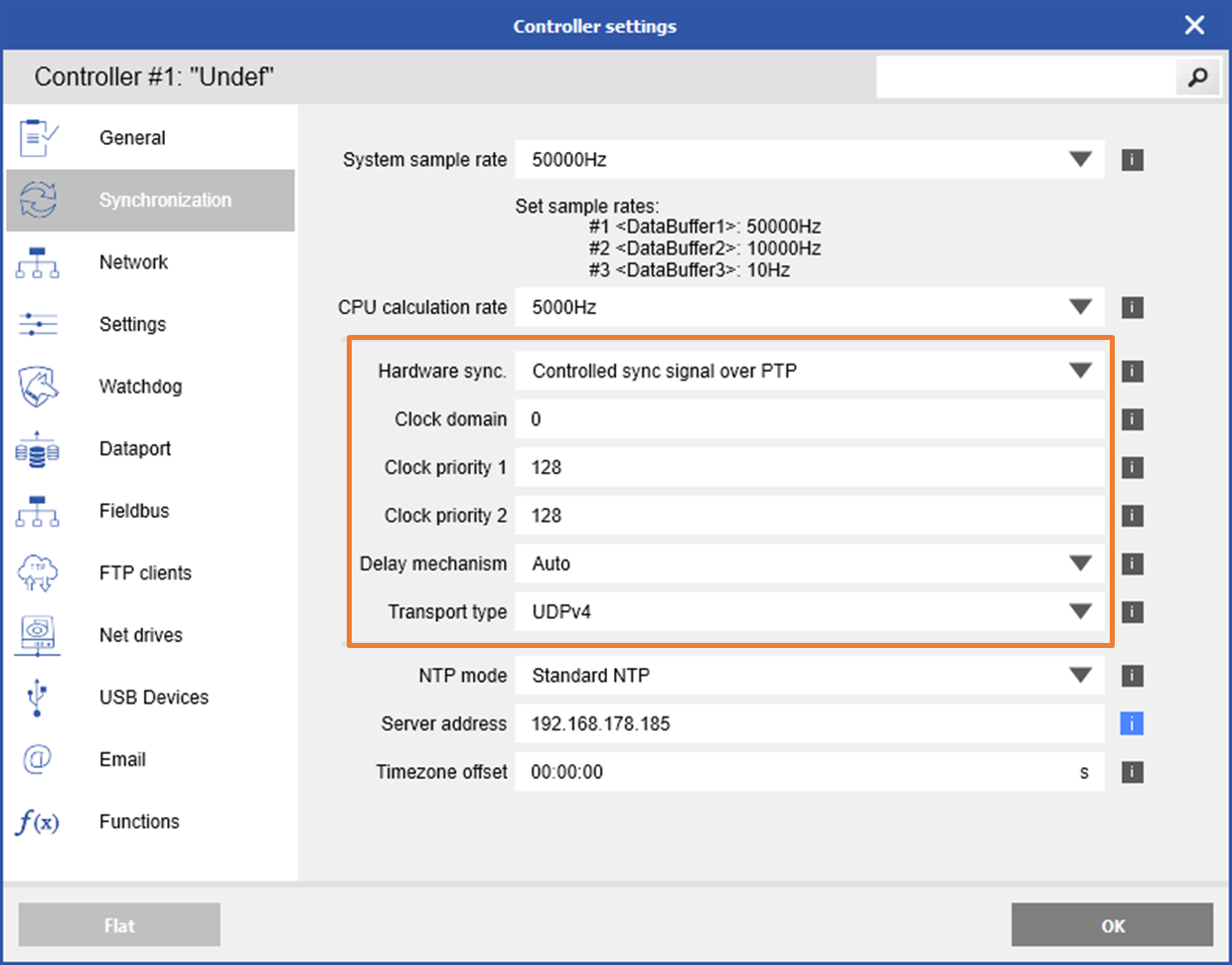
To set up the controller as an NTP client, Controller settings -> Synchronization in GI.bench. Select the Controlled sync signal over PTP and set the PTP clock parameters.

After a reboot of the controller, the controller performs a single step to synchronize its local clock with the PTP master clock. If the PTP master clock changes during operation, the controller will adjust its local time in smaller multiples of steps if the time difference is <2 seconds. However, if the time difference exceeds 2 seconds, the controller will execute a single-step synchronization instead.
IRIG-B003/B005
IRIG stands for Inter-Range Instrumentation Group, which refers to a whole group of serial time codes that use a continuous stream of binary data to transmit information on date and time. Individual IRIG code formats are distinguished by names consisting of a letter followed by a 3-digit number. The individual name determines the transmission speed and frame rate, whether the time code is modulated or unmodulated, and the kind of information included in the transmitted data.
The Q.station controllers support the following IRIG signals:
|
Format |
Encoding |
Modulation |
Carrier |
Expressions |
Bit rate |
Interval |
|
IRIG-B |
B003 |
DCLS |
N/A |
BCDTOY, SBS |
100 pps |
1 s |
|
IRIB-B |
B005 |
DCLS |
N/A |
BCDTOY, BCDYEAR, CF |
100 pps |
1 s |
- BCD - Binary Coded Decimal code contains time information including seconds, minutes, hours, and days, recycling yearly (HH, MM, SS, DDD). The BCD time-of-year code (BCDTOY) reads zero (0) hours, minutes, seconds, and the fraction of seconds at 2400 each day and reads day 001 at 2400 of day 365, or day 366 in a leap year. The BCD year code (BCDYEAR) counts years and cycles to the next year on January 1st and will count to the year 2099.
- SBS - SBS time-of-day code consists of the total elapsed seconds, recycling daily (0….86400). SBS reads zero (0) seconds at 2400 each day excluding leap second days when a second may be added or subtracted.
- CF - The CF group code contains the year, time quality, leap year, pending leap seconds, and parity. Other CF bits are reserved for user-defined purposes, depending on the application.
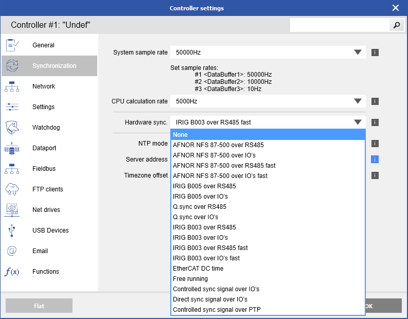
The Q.station supports IRIG TTL (over I/Os) or IRIG RS-485. To select IRIG time synchronization go to Controller settings -> Synchronization in GI.bench and select IRIG B003 over IOs or IRIB B003 over RS485.

The IRIG-B signal should be connected to DI1 (pin 2) and GND (pin 8) on the digital input connector on the Q.station X. The digital inputs should be configured for TTL logic level.
AFNOR NFS 87-500
EtherCAT Distributed Clock
The basis for deterministic behavior is precise time synchronization. EtherCAT uses a distributed clock (DC) technology per the IEEE 1588 Precision Time Protocol standard. The EtherCAT master acts as the highest-ranking clock, called the grandmaster clock, and synchronizes all other slave clocks. The distributed clock method ensures that the latency offset is compensated between all slave clocks.
Time synchronization via EtherCAT Distributed Clock is available on the Q.station X EC and Q.station 101).
To enable the Distributed Clock in the EtherCAT master, the Sync0 parameter must be activated.
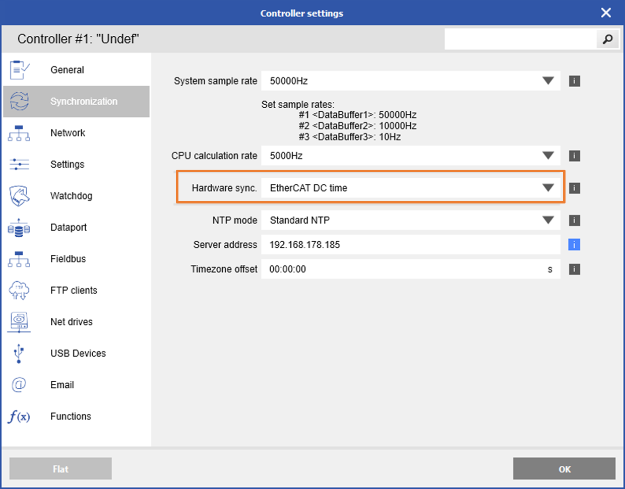
To select EtherCAT DC time synchronization go to Controller settings -> Synchronization in GI.bench and select EtherCAT DC time. Just so you know, no additional configuration settings are required.