Introduction
The Q.series controllers (Q.station 101, Q.station X, and Q.monixx) offer the option to connect a GPS receiver for time synchronization and real-time position data. They support drivers for Garmin USB devices and the NMEA 0183 standard. The NMEA data sets used by the controller include:
- $GPRMC (Recommended minimum specific GPS/Transit data)
- $GPGGA (Global Positioning System Fix Data)
GPS receivers with an RS232 interface require a USB-to-Serial converter for connecting the Q.series controller.
Recommended GPS Receivers
The following GPS receivers are recommended:
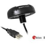
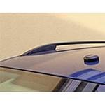
Navilock USB 2.0 Multi GNSS Receiver u-blox 8- The Navilock 62531 can be mounted on the roof of a cabinet or vehicle.
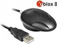
- The Navilock 62523 resembles a PC mouse and can be placed anywhere. It also features a magnetic base for secure attachment to metal surfaces.
The GPS factory default update rate is 1 Hz. To change it (up to a maximum of 10 Hz), use the u-center software from u-blox. Go to the "Rates" section and set the desired update rate. Save the settings to flash in the "Configuration" section.
Controller Configuration
-
Connect the GPS receiver to the USB port on the controller.
-
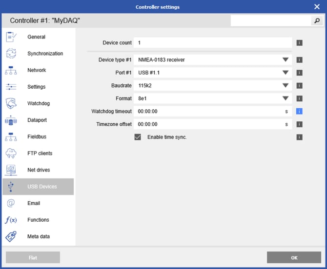
In GI.bench, double-click the controller to open the Controller Settings window and navigate to USB Devices.
-
Enter a Device count of 1.
-
Select the port to which the GPS receiver is connected.
-
Choose the type (NMEA-0183 receiver or Garmin USB-GPS receiver).
-
Enter the appropriate parameters for the baud rate and format based on the GPS receiver.
-
To synchronize the controller's time with the GPS clock, check the box for "Enable time sync".
-
Click OK to apply the changes and write updates to the controller.
Get Positioning Data Function
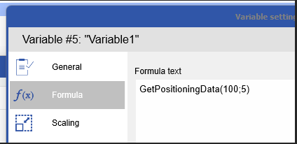
You can create arithmetic virtual variables using the GetPositioningData() function to extract additional information from the GPS signal.
GetPositioningData(Selector;InfoSelector)
Selector (defines the USB port to which the device is connected)
|
Code |
Port |
Description |
|---|---|---|
|
100 |
USB0 |
right port |
|
101 |
USB0 Hub Port0 |
right port |
|
102 |
USB0 Hub Port1 |
right port |
|
103 |
USB0 Hub Port2 |
right port |
|
104 |
USB0 Hub Port3 |
right port |
|
200 |
USB1 |
left port |
|
201 |
USB1 Hub Port0 |
left port |
|
202 |
USB1 Hub Port1 |
left port |
|
203 |
USB1 Hub Port2 |
left port |
|
204 |
USB1 Hub Port3 |
left port |
If a USB hub is connected to USB port 1, the first port on the hub is numbered 101, and the second port is numbered 102. If the hub is connected to USB port 2, the first port on the hub is numbered 201, the second 202, and so on.
InfoSelector
|
Code |
Meaning |
Description |
Device / Command |
|---|---|---|---|
|
0 |
Time |
TimeOLE2 (days since 01.01.1900) |
Garmin GPS / GGL, GGA, RMC |
|
1 |
Latitude |
Degrees and minutes |
Garmin GPS / GGL, GGA, RMC |
|
2 |
Longitude |
Degrees and minutes |
Garmin GPS / GGL, GGA, RMC |
|
3 |
Speed |
[knots] |
Garmin GPS / RMC |
|
4 |
Heading |
[°] |
Garmin GPS / RMC |
|
5 |
Number of satellites |
Number of satellites being tracked |
Garmin GPS / GSV, GGA |
|
6 |
Altitude above NN |
[m] |
Garmin GPS / GGA |
|
7 |
Quality |
State |
GGA |
|
8 |
Horizontal dilution of position |
GGA |
|
|
9 |
Rate and direction of turn |
ROT |
|
|
10 |
Longitudinal water speed |
VBW |
|
|
11 |
Transverse water speed |
VBW |
|
|
12 |
Longitudinal ground speed |
VBW |
|
|
13 |
Transverse ground speed |
VBW |
|
|
14 |
Track degrees: true |
VTG |
|
|
15 |
Track degrees: magnetic |
VTG |
|
|
16 |
Depth below transducer |
[feet] |
DBT |
|
17 |
Depth below transducer |
[m] |
DBT |
|
18 |
Depth below transducer |
[fathoms] |
DBT |
|
19 |
Water: depth |
[m] |
DPT |
|
20 |
Water: offset from the transducer |
DPT |
|
|
21 |
Wind: angle |
[°] |
MWV |
|
22 |
Wind: speed |
MWV |
|
|
23 |
Water: temperature |
[°C] |
MTW |
|
24 |
Own ship data: heading |
[°] |
OSD |
|
25 |
Own ship data: vessel course |
[°] |
OSD |
|
26 |
Own ship data: vessel speed |
OSD |
|
|
27 |
Own ship data: vessel set |
[°] |
OSD |
|
28 |
Own ship data: vessel drift |
OSD |
|
|
29 |
RADAR system data: cursor range |
RSD |
|
|
30 |
RADAR system data: cursor bearing |
[°] |
RSD |
|
31 |
RADAR system data: range scale |
RSD |
|
|
32 |
Heading degrees: true |
[°] |
HDT |
|
33 |
Speed |
[knots] |
VTG |
|
34 |
Speed |
[km/h] |
VTG |
|
35 |
Latitude (Decimal) |
[°] |
GGL, GGA |
|
36 |
Longitude (Decimal) |
[°] |
GGL, GGA |
|
100 |
Error states |
State |
It might be possible that it won´t work if you use the GPS mouse inside. For verification you could use the function "number of satellites"
Converting knots:
-
m/s = knots * 0,514
-
km/h = knots * 1.852
-
mph = knots * 1.15
Converting latitude and longitude:
- XXYY.ZZZZ ⇒ XX° + (YY.ZZZZ / 60)°
- XXYY.ZZZZ ⇒ XX° YY’ (0.ZZZZ * 60)’’