Table of Contents
- System Preparation
- System Assembly
- 100 kHz System Configuration
- Software Setup
- Q.station Setup
- Sample Rate Configuration
- Synchronization via SNTP
- Update the Internal Real Time Clock
- Synchronizing Multiple Q.stations
- PAC Functionality
- Digital Inputs and Digital Outputs
- UART Configuration
- EtherCAT
- Ethernet Settings
- CAN bus Interface
- Modbus Interface
- Other Virtual Variables
- Storage Methods
- Data Logger Configuration
- VNC Compatibility
- Index
System Preparation
Introduction
Thank you for selecting Gantner Instruments as your data acquisition solution. This quick start guide will discuss installing and setting up your Q.station as a fully autonomous data concentrator. Use this guide along with the Q.station manual for complete details.
Software Requirements
The Q.station requires GI.bench (previously test.commander) to perform all setup and configuration tasks, including sample rate changes, firmware updates, interface setups, and data logging.
Separate software called test.con configures the PAC functionality and the optional built-in display of a “T” version Q.station.
Other Gantner software tools not discussed within this guide can be explained on a project-by-project basis. Contact us today!
Software Downloads
GI.bench: https://resources.gantner-instruments.com/en/gi-bench-download
test.commander: https://gi-productbase.gantner-instruments.com/en/rest_api/downloads/public/46/
test.con: https://gi-productbase.gantner-instruments.com/en/rest_api/downloads/public/362/
PC Requirements
Minimum OS: Windows 7
Recommended RAM: 8 GB
Recommended Processor: Dual Core (2+ GHz)
Data Storage: Depends on application requirements
1 x Ethernet port (minimum)
1 x USB port (minimum)
Accessories
Ethernet Cable (CAT5E or better)
Electrical Wire (18-22 AWG)
Power Supply (10-30 VDC)
35 mm DIN Rail (if planning to mount Q.bloxx hardware)
System Assembly
Assembling the Controller
- After unpacking the controller, the first thing to determine is where to mount the unit. The Q.station 101 includes a built-in DIN rail clip located on the back of the unit (shown in image below).
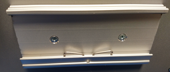
- Hook the clip's bottom portion onto the DIN rail's bottom portion.
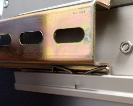
- With the bottom portion partially latched, push the Q.station up, causing the top portion of the clip to latch to the top portion of the DIN rail.
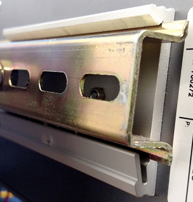
- If the Q.station needs to be moved to another location, push the Q.station up to disconnect the top portion of the mount first. The bottom portion will then slide off.
- The Q.station has 4 x blue terminal blocks (3 x 10-Pin and 1 x 4-Pin). Connect the terminal blocks to their respective ports on the Q.station (bottom side).
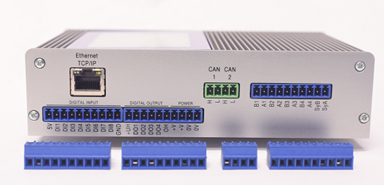
- Using the image above, let’s review the purpose of each connector. Starting from left to right:
- This connector connects up to 8 x digital inputs to the Q.station. Auxiliary +5V is available on the first pin. Setting the switching thresholds will be explained in another section in this guide.
- Max input voltage: 30 VDC
- Max input current: 1.5 mA
- This connector connects up to 4 x digital outputs from the Q.station. The 1st digital output is designated as a watchdog signal (configuration will be explained later). The remaining outputs can be freely configurable. These outputs must be powered via +UH and OH.
- Max voltage supply: 30 VDC
- Max current supply: 100 mA
-
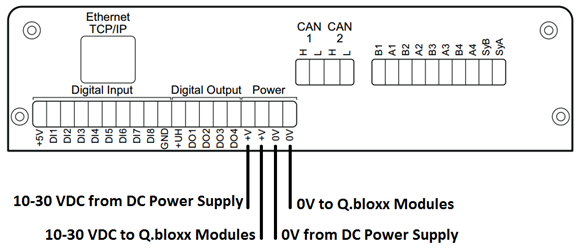
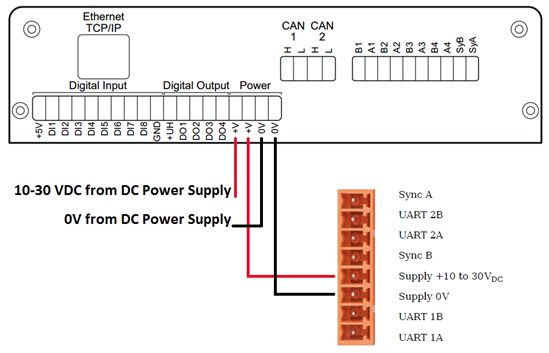
This connector is also used to connect the supply voltage used to power the Q.station. There are 2 x Pins available for the supply line (+V) and 2 x Pins for 0V. The 2 x supply Pins are connected internally, likewise for the 2 x 0V Pins.
- Power supply: 10-30 VDC
- Power consumption: approximately 12 W
- This 4-pin connector is used to interface to the CAN port on a Q.station. It may be required to wire a resistance across these two pins for bus termination.
- CAN 1 – H = CAN 1 High
- CAN 1 – L = CAN 1 Low
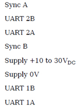
- This connector allows Q.bloxx modules to connect to the Q.station’s 4 x UARTs.
A1 – UART1, A
B1 – UART2, B
etc.
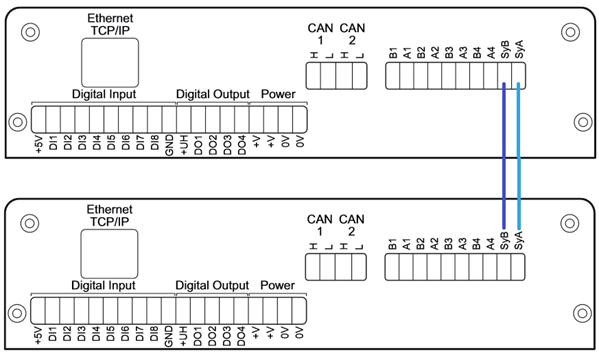
This connector also provides 2 x Pins for synchronization of multiple controllers. Connect SyA from the master controller to the slave, likewise for SyB.
- This connector connects up to 8 x digital inputs to the Q.station. Auxiliary +5V is available on the first pin. Setting the switching thresholds will be explained in another section in this guide.
- On the same side as the 4 x blue terminal blocks is the Ethernet TCP/IP port. More specifically, a Gigabit Ethernet port is used for data transfer between the Q.station and the host system. Connect your CAT5 Ethernet cable to this port.
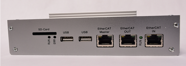
- The other interfaces and ports on the Q.station are located on the top side. These connections include:
- SD card slot
- 2 x USB ports (USB 2.0)
- EtherCAT IN and OUT ports
Powering the Controller
The Q.station 101 requires 10-30 VDC (approx. 12 W).
- Connect 10-30 VDC to one of the +V Pins on the power connector.
- Connect 0V to one of the 0V Pins on the power connector.
- If the power supply was sized correctly to provide power to the Q.station and Q.bloxx modules, the other +V and 0V Pins on the Q.station could be wired to the Q.bloxx modules.
Connecting Slave Modules (i.e., Q.bloxxs)
After mounting the Q.station onto the DIN rail and wiring the power supply, it is now time to connect the Q.station to the slave modules via the available UARTs.
- Mount the Q.bloxx to the desired location. The Q.bloxx can mount onto the same DIN rail as the Q.station.
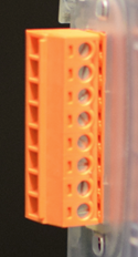
- A group of Q.bloxx modules connected requires a connector to connect power and communications to a Q.station. This connector is a Q.bloxx-CONL8O:
- The overall length of the cable between the Q.station and the measurement modules on a given UART will determine the maximum possible speed of that UART.
Cable Length (meters)
Maximum Baud Rate
1000
< 500 kBd
100
< 1500 kBd
20
< 6000 kBd
10
> 6 to 24 MBd
- Terminating resistances must be activated on the last base of each UART (only there). This is done to prevent reflections on the line that could lead to disturbances or loss of data transmission. Terminating resistances are not required on the Q.station (built-in).
- Connect 10-30 VDC from the Q.station to 10-30 VDC on the Q.bloxx-CONL8O. Similarly, connect 0V from the Q.station to 0V on the Q.bloxx-CONL8O.
100 kHz System Configuration
The Q.station can be configured with a max sampling rate of 100 kHz with a max 8 channels (The Q.station X can support 16 channels at 100 kHz). This means that the sensors are monitored and signal conditioned at 100 kHz, and the data is updated to the host system at a rate of 100 kHz. To create this system, the following setup is required:
- 1 x Q.station with 4 x A101 modules
- 1 x A101 module connected to each UART (4 x UARTs per Q.station)
- 2 x 100 kHz channels per A101 module
- 8 x 100 kHz channels per Q.station
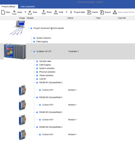
Sample Rate Configuration:
Module Layout:
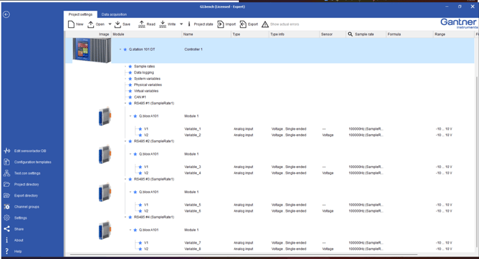
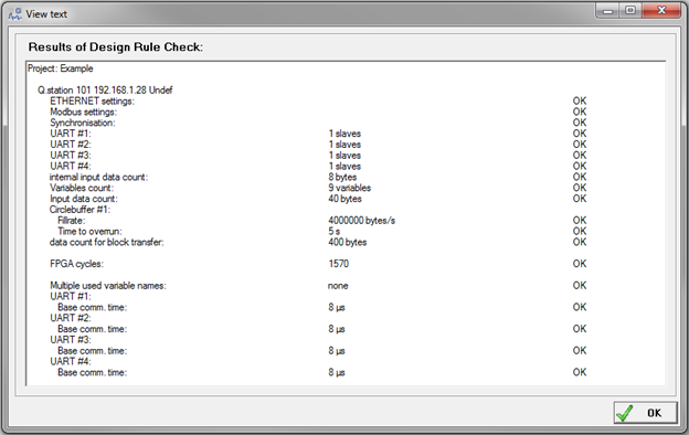
System Check:
GI.bench automatically checks the configuration. Any errors will be shown with a warning. test.commander can be seen by going to File > Calculate Statistics > Check
Software Setup
GI.bench Installation
- Download the GI.bench software from the Gantner Instruments website.
- Install the GI.bench software onto the test PC.
- Run the GI.bench software. If it is the first time running GI.bench on the current PC, select either the free configuration version or activate with purchased Ticket-ID license (or GI.bench USB dongle license)
test.commander Installation
- Download the test.commander software from the Gantner Instruments website.
- Install the test.commander software onto the test PC.
- Run the test.commander software. If it is the first time running test.commander on the current PC, the test.commander license must be entered to change the mode from DEMO to LICENSED to unlock full functionality.
About > License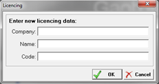
- Sometimes it is necessary to switch the language settings of test.commander. If test.commander installs with the German setting, switching to English is easily accomplished:
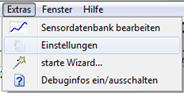
Select Extras > Einstellungen
Select Sprache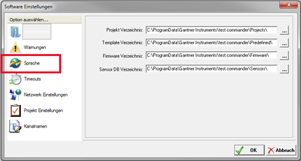
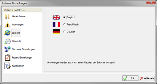
Select English. The software must be restarted for changes to take effect.
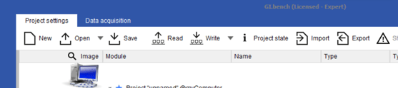
- A new project can now be created.
PC Setup
Before connecting to the hardware, it is important to check the Firewall and Ethernet settings on the PC to ensure a seamless connection.
https://knowledge.gantner-instruments.com/firewall-and-network-settings-guide
Q.station Connection
Pre-requisites:
- Controller and Q.bloxx modules have updated firmware
- Q.bloxx modules have proper address settings
- Create a new project (GI.bench: project settings tab > New, test.commander: File > New Project).
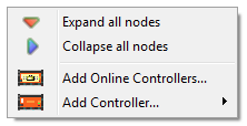
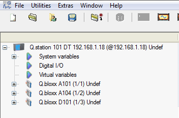
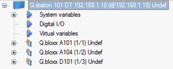
- GI.bench: Read, select Q.station, test.commander: Right-click on the mouse and select Add Online Controllers.
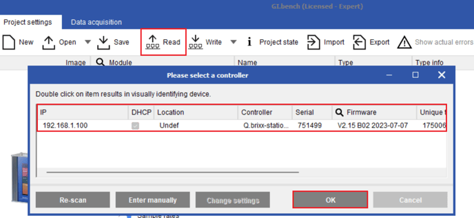
If the firewall and IP settings are correctly configured, all attached controllers will be displayed. Highlight the controller to connect to and select OK.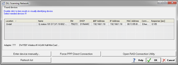
- The complete configuration, including the attached slave modules, will be added to the project.
Q.station Setup
To apply any setting changes performed in test.commander, update the project to the controller: File > Write Project (Update).
Sample Rate Configuration
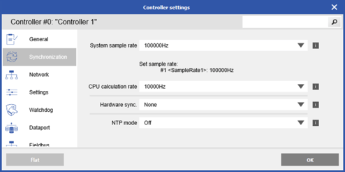
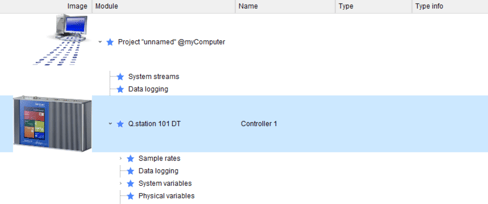
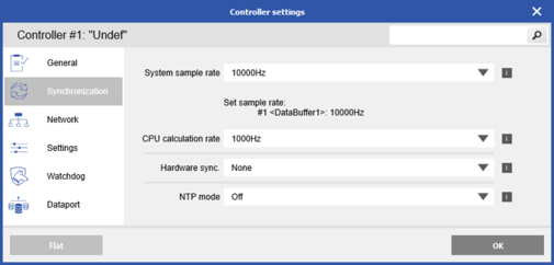
- Double-click on the Q.station.
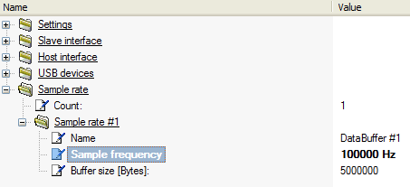
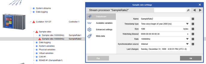
- Navigate to the Synchronization section (test.commander: Sample rate). Configuring up to 4 individual sample rates in a single Q.station is possible. Enter the value in the Count option. The 1st sample rate is the master rate; all other sample rates can be the same or less than this 1st sample rate.
Give the sample rate a specific name and specify the size of the buffer. There is 200 MB available on a single Q.station. This means that all configured buffers must share this 200 MB of space.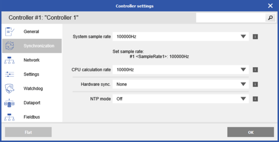
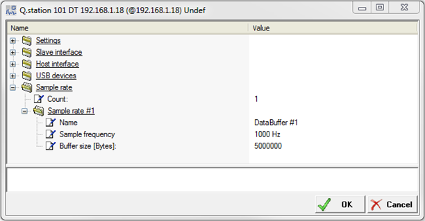
- The 1st buffer receives its synchronization from the internal time clock of the Q.station. If used, the remaining buffers (i.e., 2-4) can be synchronized from the internal time clock or an external signal (digital input on the Q.station). Click the OK button to apply all the changes.

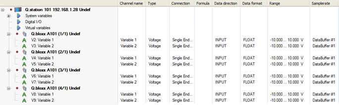
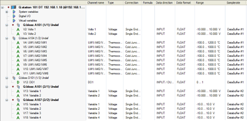
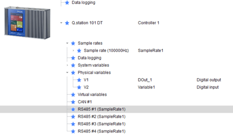
- In the project page, we can view all attached slave modules and their channels. We can assign channels to a specific sample rate using the Samplerate column.
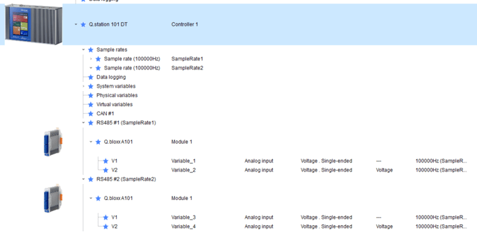
Rule: The channels on a single UART can be assigned to a single buffer only. In the example above and below, channels on UART1 are in DataBuffer #1, and channels on UART2 are in DataBuffer #2.
Synchronization via SNTP
- Set up an SNTP service on the attached PC or refer to an online location. A separate guide on how to perform this is available on the Gantner Instruments knowledge-base: https://knowledge.gantner-instruments.com/windows-pc-as-a-ntp-time-server
- Double-click on the Q.station
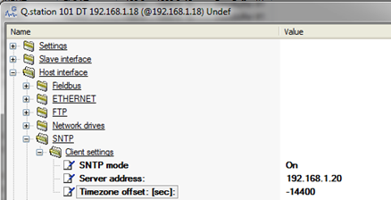
- Navigate to synchronization (test.commander: Host interface > SNTP > Client settings). Change SNTP mode.
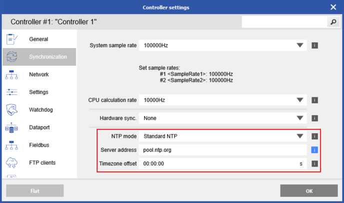
- After previously configuring the SNTP service on the PC, enter the Server address (i.e., the static IP address of the PC).
- Also, enter the Timezone offset in seconds. This is the offset from UTC compared to the controller’s current location.
- This provides a constant synchronization between the Q.station and the PC (as long as the PC is running and an Ethernet cable between the PC and Q.station is connected).
Update the Internal Real Time Clock
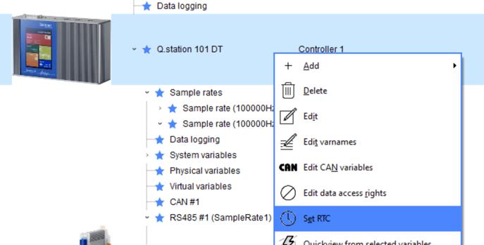
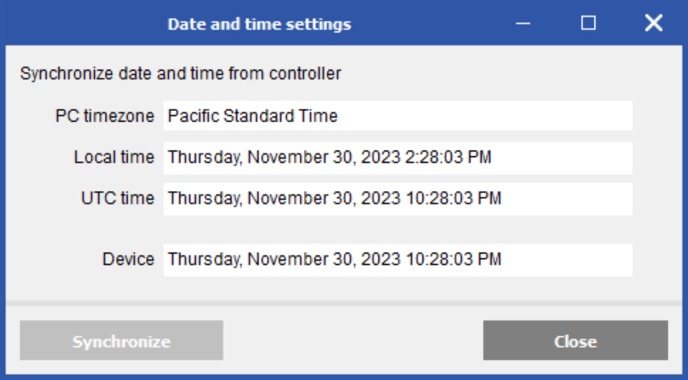
- GI.bench: right-click Q.station > Set RTC
- Click Synchronize to sync to UTC time. GI.bench will then handle the offset based on PC's location
- Click Synchronize to sync to UTC time. GI.bench will then handle the offset based on PC's location
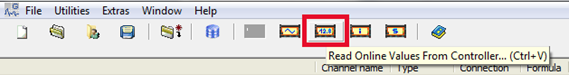
- test.commander: Click on the Read Online Values From Controller button.
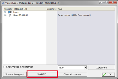
- The View values window will appear. Click on the Set RTC button.
- Make sure the radio button next to Use local PC time is selected.
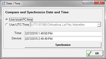
- Click the Synchronize button. The device (i.e., Q.station) will be synched to the time on the PC.
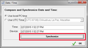
- The View values window will appear. Click on the Set RTC button.
- This performs a one-time synch of the Q.station. The RTC (real-time clock) inside the Q.station is battery-backed; therefore, the time is saved even if the power to the controller is reset.
Synchronizing Multiple Q.stations – Q.sync over RS485
There are multiple ways to synchronize multiple Q.stations together. The first method is to synchronize all Q.stations within a single system to a common source (i.e., all synched to the same PC via SNTP). Within this section, we will describe the Gantner protocol called Q.sync over RS485.
- Using the Q.sync over RS485 method: Setup 1 x Q.station as the master, all other Q.stations connected to this master Q.station are considered slaves and obtain their time synch from this master.
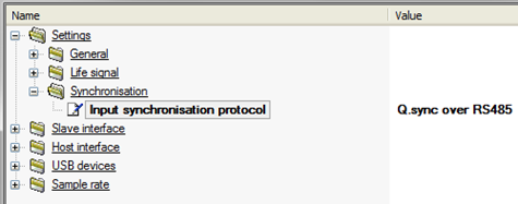
- Designate the master Q.station. Connect this unit to GI.bench/test.commander. Double-click on the controller and navigate to Settings > Synchronization. Make sure the Input synchronization protocol is set to none. This means that the Q.station is a master unit.
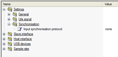
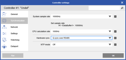
- In a similar process, connect each slave Q.station one at a time to test.commander. Double-click on the controller and navigate to Settings > Synchronization. Make sure the Input synchronization protocol is set to Q.sync over RS485.
- Using an electrical wire, connect SyA from the master Q.station to SyA of the slave Q.station. Repeat the process for SyB. The maximum length that these cables can be is 400 meters.
PAC Functionality
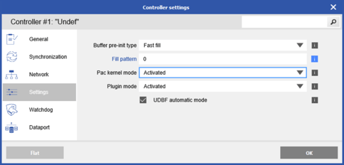
A custom program built-in test.con can be downloaded and run on a Q.station-101T or Q.station-101DT controller. Before downloading a program to the controller, we need to verify that the PAC functionality of the controller is activated.
With the Q.station loaded in test.commander, double-click on the Q.station and navigate to Settings. Make sure PAC Functionality is set to activate.
Creating a test.con program with a Q.station: https://knowledge.gantner-instruments.com/quick-start-guide-test.con-and-hmi-introduction

Digital Inputs and Digital Outputs
Threshold:
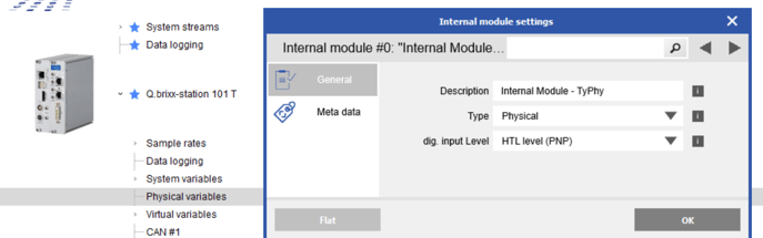
- GI.bench: Double-click the physical variables section under the Q.station. Change the dig. input level between HTL and TTL
TTL levels: <1V and >3.5V
PLC levels: <7V and >8V
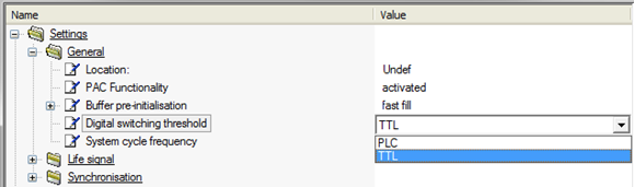
- test.commander: Double-click on the Q.station and navigate to Settings > General. The digital switching threshold can be set to TTL or PLC level.
Life Signal / Watchdog:
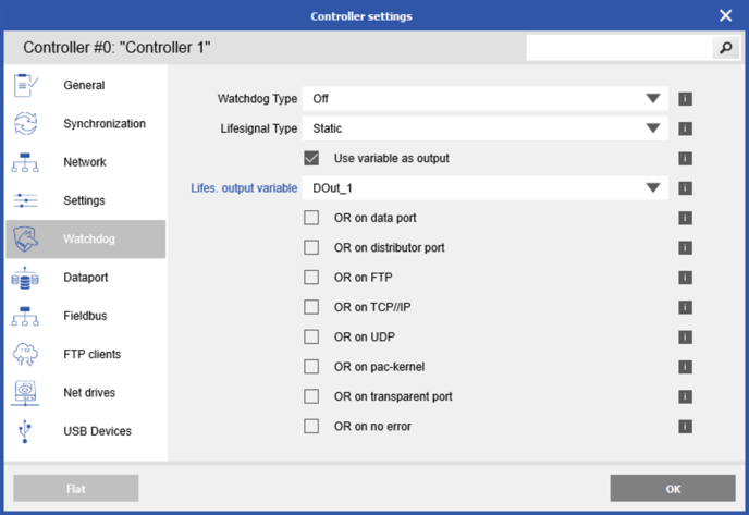
- GI.bench
- Create a digital output under the system variables section
- Double-click the Q.station and navigate to the Watchdog section. Check the box for use variable as output and select the digital output
- test.commander: The DO1 can be used as a life signal for the Q.station. Double-click on the Q.station and navigate to Settings > Life Signal.
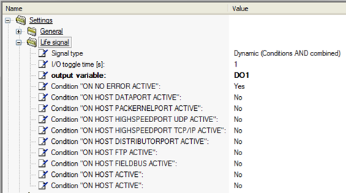
- The signal type conditions can be set to ANDs or ORs.
- The toggle time for the output signal can be set between 1 to 3600 seconds.
- The life signal can either be turned off (deactivated) or turned on (set to DO1)
- The 10 x individual conditions can be set to Yes or No.
Freely Configurable Digital I/O:
- 8 x DI and 4 x DO are available on 1 x Q.station 101. (6 digital inputs only on other Q.station types)
- GI.bench: right-click the Physical variables section and select Add
- Double-click the created variable and change type between digital input or output
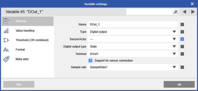
- Double-click the created variable and change type between digital input or output
- test.commander: The Digital I/O’s can be configured inside test.commander, underneath the Q.station:
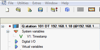
- Right-click on Digital I/O and select Add variable. Choose DIGITAL_INPUT or DIGITAL_OUTPUT.
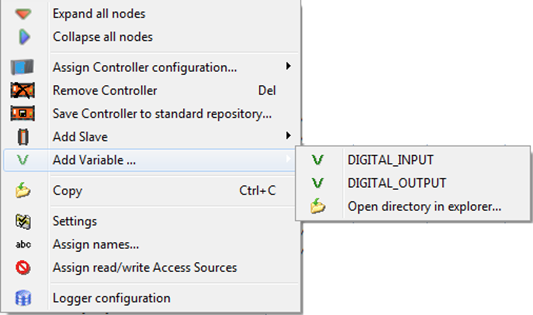
- Right-click on Digital I/O and select Add variable. Choose DIGITAL_INPUT or DIGITAL_OUTPUT.
-
- The new Digital variables will be added under the Digital I/O section:
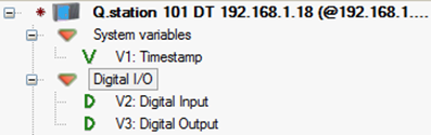
- The new Digital variables will be added under the Digital I/O section:
-
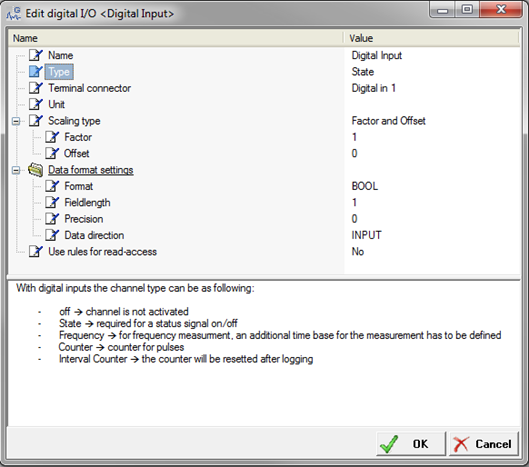
- Double-click on the variable to modify.
- Double-click on the variable to modify.
- The following can be modified for each channel:
- Name
- Type
- Unit
- Scaling Factor
- Data Format
UART Configuration
There are up to 4 x individual UARTs on a single Q.station, and each can be configured independently of one another.
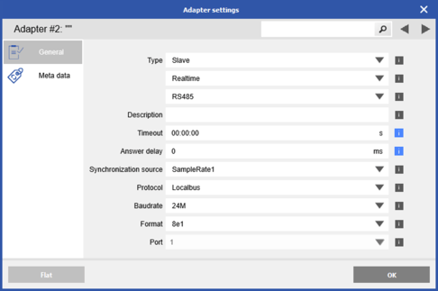
- In GI.bench, double-click one of the RS485 sections
- Change the sync source and baudrate as needed
- Change the sync source and baudrate as needed
- In test.commander, double-click on the Q.station and navigate to Slave interface.
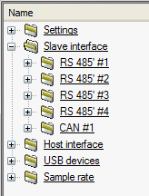
- The 4 x UARTs are displayed here. Open each to configure the available settings.
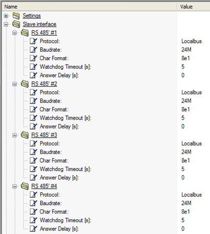
- The 4 x UARTs are displayed here. Open each to configure the available settings.
- All UARTs utilize the Gantner Localbus protocol. This is a special communication protocol used for data transmission between Gantner controllers and Gantner measurement modules (e.series and Q.series)
- The main setting to be aware of in this section is the Baud rate of the UART. Depending on the sample rate of the buffer that the UART is assigned to, number of channels connected to that UART, and the physical distance of the UART, it may be necessary to reduce or increase the baud rate.
- The maximum baud rate can be set to 24M (Q.station X can support 48M), typically used for update rates 1 kHz or greater. For slower update rates, it might be necessary to reduce the baud rate to prevent errors.
EtherCAT
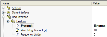
- The Q.station can be used as an EtherCAT slave device. In GI.bench go to the Fieldbus section (In test.commander, double-click on the Q.station and navigate to Host interface > Fieldbus).
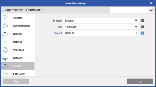
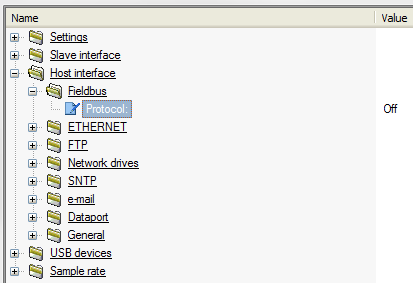
- To turn the interface on, set the Protocol to Ethercat. If this interface is not being used, it is best to keep it disabled (i.e., Protocol set to Off).
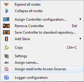
- Right-click on the Q.station and select Edit data access rights (test.commander: Assign read/write Access Sources)
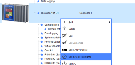
- Select which variables are available via the EtherCAT protocol; use the Fieldbus column to check off these variables.
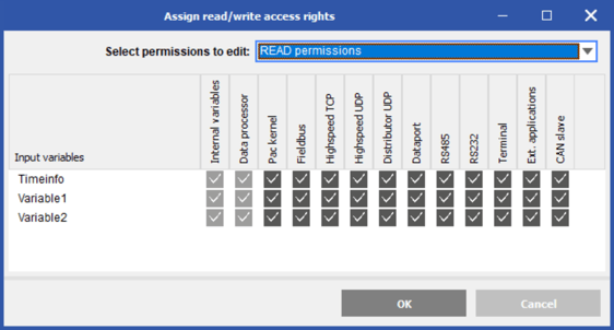
- Only the channels configured for EtherCAT usage get the required PDOs.
- An EtherCAT master that connects to Gantner EtherCAT slave devices should provide the following abilities:
- Handle ENI files
- Read object dictionaries via CoE
- The Gantner ESI file (Gantner Instruments.xml) can be obtained from the following directory:
GI.bench: C:\Users\Public\Documents\Gantner Instruments\GI.bench\additionals\EtherCAT
test.commander: C:\Users\Public\Documents\Gantner Instruments\test.commander\Additionals\EtherCAT - The total number of variables is limited to 253 inputs and 253 outputs on a single Q.station.
Ethernet Settings
The Ethernet port on the Q.station is the main interface used for data transmission and system configuration. A Q.station communicates to a PC using one of the following 2 methods:
- Direct connection using a static IP address
- Via a network using DHCP
- STATIC IP ADDRESS – The quickest and easiest way to communicate with any Gantner test controller is to set your PC to a static IP address on the same subnet as the Gantner controller.
- By default, a Q.station ships from the factory with a dynamic IP setting. An example of a static connection is that the PC should have a static IP address of 192.168.1.X, where X is a number different than the Q.station
- If the PC requires a different static IP address than shown above, the Q.station’s static IP address can be modified. To do so, ensure the Q.station is connected directly to the PC via an Ethernet cable. GI.bench: Read > Select controller > Change settings
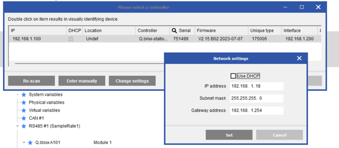
In test.commander, select Utilities > Controller Network Terminal.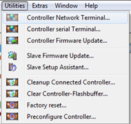
The network finder window will appear and display all connected controllers, even if the controller is on a different subnet than the PC.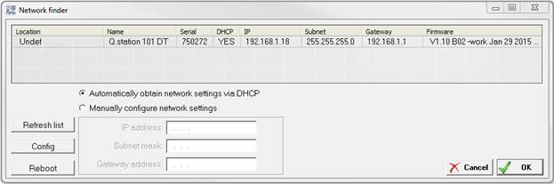
Highlight the controller to modify, and select the radio button next to configure network settings Manually. Type the desired static IP address, subnet mask, and gateway address.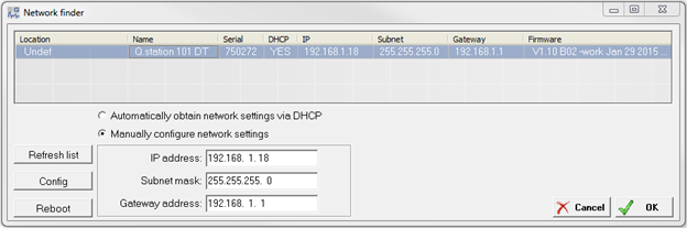
To apply the settings, press the Config button. The software will update the settings and restart the device. - With the PC & Q.station on the same subnet and each with a unique static IP address, we can easily connect the controller to test.commander for system configuration.
- DYNAMIC IP ADDRESS – This method is used when a Q.station and PC are both connected to the same network via a switch or a router. We must ensure the DHCP feature is enabled on the controller to accomplish this. To do so, connect to the Q.station using the STATIC IP ADDRESS method first to ensure the DCHP is enabled. In the image above, ensure the Use DHCP server is set to Yes.
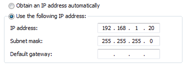
- Connect the Q.station and PC back to the same network. Ensure the PC obtains an IP address automatically from the network (i.e., using DHCP). The IP address settings of the PC should look something like this:
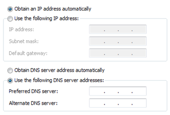
- The Q.station can now be connected to test.commander since the Q.station is also obtaining an IP address automatically (i.e., DHCP).
CAN bus Interface
The single CAN bus port on a Q.station can be used for inputs and outputs. Make sure to configure the baud rate of the CAN bus.
GI.bench: Double-click the CAN #1 section
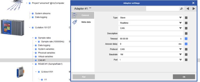
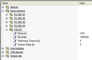
test.commander: Double-click on the Q.station and navigate to Slave interface > CAN.
For GI.bench instructions: https://knowledge.gantner-instruments.com/configuring
test.commander below:
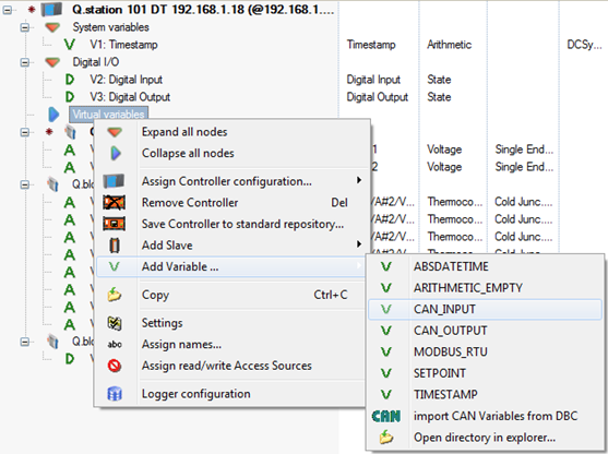
- CAN INPUTS – A Virtual variables section is available underneath the Q.station. Right-click on this section and select Add Variable > CAN_INPUT.
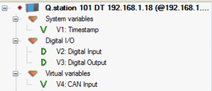
- A new blank CAN Input variable will be available in the Virtual Variables section.
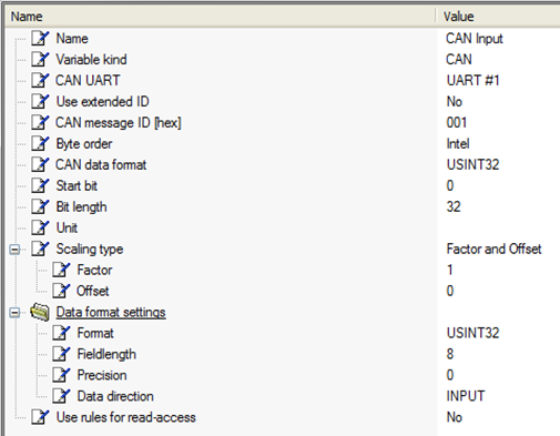
- Double-click on the variable to modify its settings.
- CAN Database file is available; press the CAN DB button to find this database file on the PC. Select the CAN variable in the database file to populate all the settings for the selected variable.

Select the CAN variable from the database file: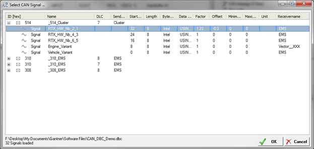
All the settings for this CAN variable will be populated.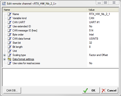
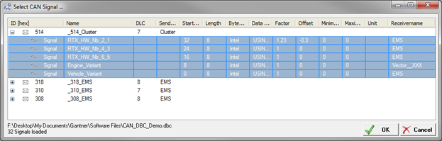
- It is also possible to import multiple CAN variables in one step. Right-click on the Virtual variables section under the Q.station and select Add Variable > import CAN Variables from DBC:
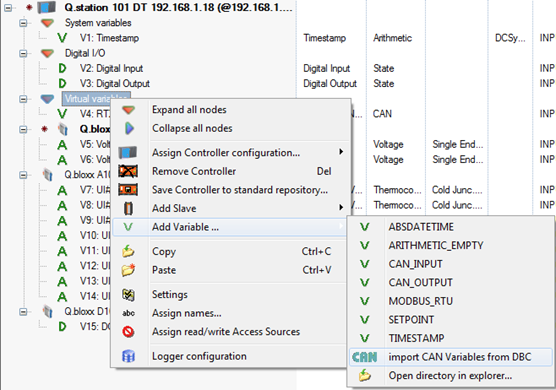
- Highlight the variables to add and click the OK button.
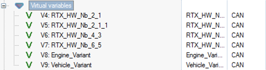
- The newly imported CAN variables can be found in the Virtual Variables section:
- CAN OUTPUTS – All variables connected to a Q.station can be sent via the CAN port as output variables. Create and configure the real and other virtual variables under normal circumstances.
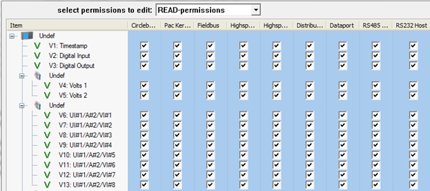
- Highlight the Q.station and select the CAN configuration button in the top toolbar of test.commander.
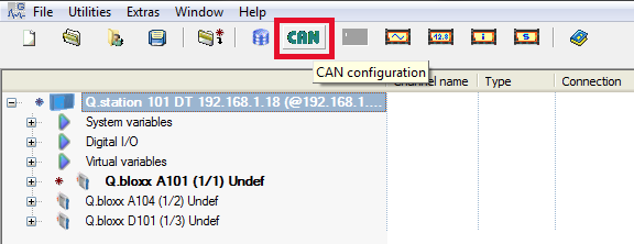
- The CAN configuration window will appear. It will display all configured channels in the system, including all real and virtual variables.
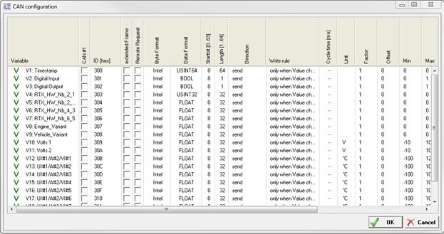
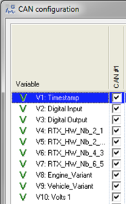
- Place a checkmark in the CAN #1 column next to each variable to output via the CAN port.
- Two variables can be included in each CAN message. Make sure the two variables have the same ID but have unique start bits.
- Modify the other settings, including byte format (Intel or Motorola), data format, start bit and bit length, data direction, and more. Click the OK button to apply the settings.
- The length of the CAN bus interface will determine the maximum baud rate that can be configured. Configuring the baud rate of the CAN port on a Q.station only modifies the settings of the Q.station. Apply the same baud rate settings on the external CAN device. Use the table below as a guide:
|
Cable Length (meters) |
Maximum Baud Rate |
|
1000 |
< 50 kBd |
|
100 |
< 500 kBd |
|
50 |
< 800 kBd |
|
25 |
< 1 MBd |
Modbus RTU Interface
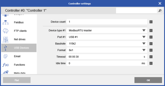
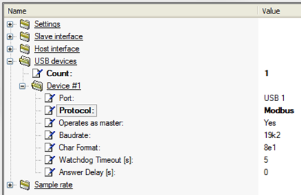
- The Q.station can as a Modbus RTU master or slave device. Double-click on the Q.station and navigate to USB devices.
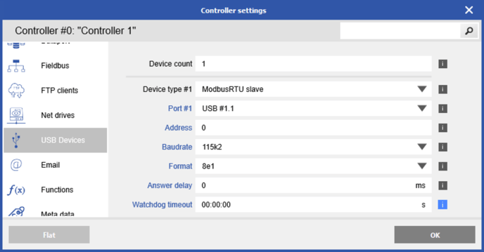
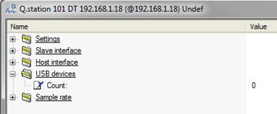
- Change the count from 0 to 1. Select USB 1 as the port. Change the protocol to Modbus. Modify the Modbus settings, including baud rate, character format, etc. Click OK to save the settings.
- GI.bench
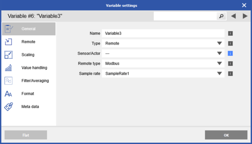
- Right-click Virtual variables and add a new variable
- Change the type to Remote and remote type to Modbus
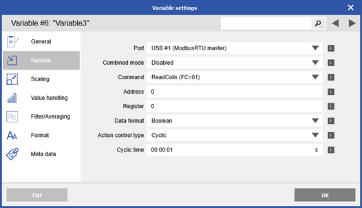
- Modify the port, mode, command, address, register, etc.
- test.commander:
- Right-click on the virtual variables section and select Add Variable > MODBUS_RTU:
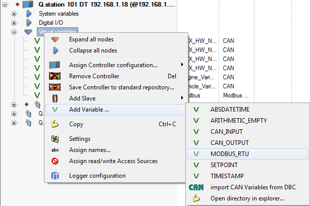
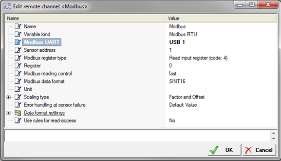
- A new Modbus variable will be added. Double-click on this variable to open the configuration window.
- Set the Modbus UART to USB 1 and modify the remaining variable settings.
- Right-click on the virtual variables section and select Add Variable > MODBUS_RTU:
Other Virtual Variables
Aside from the CAN and Modbus variables described above, it is also possible to create customizable arithmetic channels and set points inside a Q.station.
- GI.bench
- Right-click Virtual Variables and add a new variable
- Change the type to Arithmetic
- Navigate to the formula section and modify formula with functions and variables as needed
- test.commander:
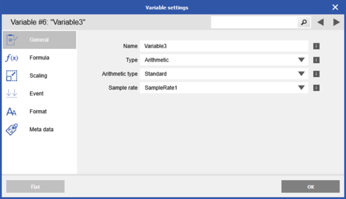
- Right-click on the virtual variable section and select Add Variable > ARITHMETIC_EMPTY or SETPOINT.
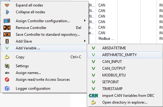
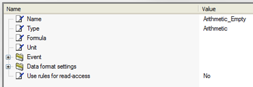
- A new virtual variable will be created. Double-click on the variable to modify its settings.
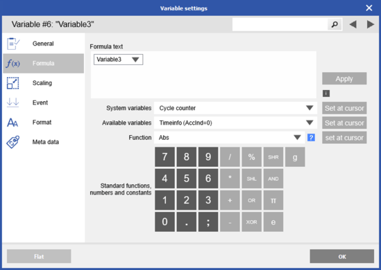
- Specifically for an arithmetic channel, the function of the channel can be created by selecting the Formula row.
- The edit formula window will appear. Create the formula for the variable using other variables in the system, mathematical operations (add, subtract, multiply, and divide), and pre-loaded functions.
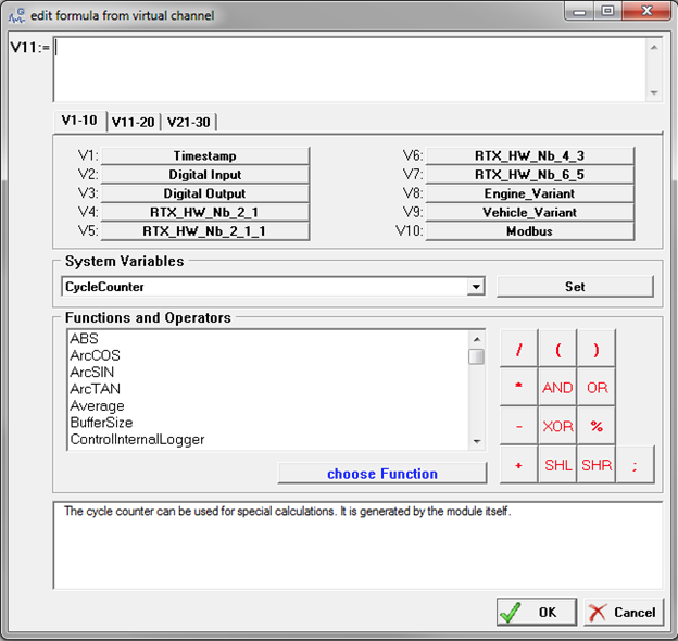
- Make sure to click the OK button to save the changes.
- Right-click on the virtual variable section and select Add Variable > ARITHMETIC_EMPTY or SETPOINT.
Storage Methods
Several other storage methods are available on the Q.station aside from the typical USB and SD card solutions. These methods include data transfer to a PC via FTP, saving directly to a network drive, and sending data via E-mail.
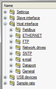
To enable and configure these settings, double-click on the Q.station to go to the controlelr settings. In GI.bench, there are separate sections for FTP, Network Drives, and Email. 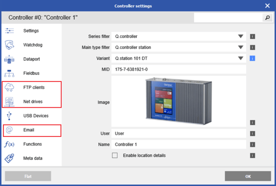 In test.commander navigate to the Host interface, where FTP, Network drives, and e-mail are all available.
Below are useful guides that will explain in more detail how to set up these useful interfaces:
- FTP – https://knowledge.gantner-instruments.com/ftp-logging
- Network Drives – https://knowledge.gantner-instruments.com/how-to-send-data-from-q.station-to-network-drive
- E-mail – https://knowledge.gantner-instruments.com/email-logging
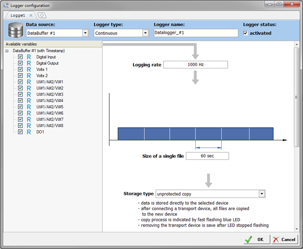
Data Logger Configuration
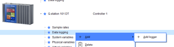
The Q.station is equipped with a dynamic and flexible data logger. This data logger is configured using test.commander. In GI.bench > right-click the Data logging section and add a new logger
In test.commander, highlight the controller, and select the data logger configuration button: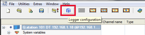
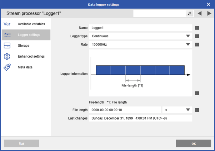
The Logger configuration window will appear. Use the Q.station Data Logger Configuration Guide for complete details on how to prepare this feature:
GI.bench: https://knowledge.gantner-instruments.com/q.station-data-logger-guide-gi.bench
test.commander: https://knowledge.gantner-instruments.com/q.station-data-logger-guide-test.commander
VNC Compatibility
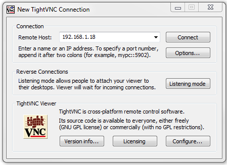
- Download a VNC viewer from the internet: http://www.tightvnc.com/
- Install the VNC viewer onto the PC.
- Run the program and make sure the Q.station is connected to the PC (with an Ethernet cable or wirelessly via a wireless router). Enter the static IP address of the Q.station.
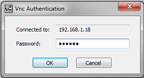
- After clicking on the Connect button, the software will prompt you to enter a password. Enter master as the password and click OK.
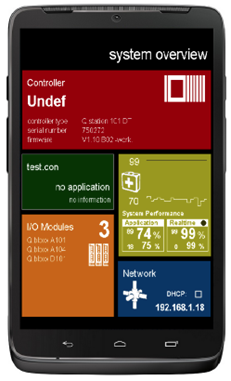
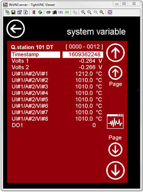
- The VNC viewer will display the screen of the Q.station. This screen is the same screen on a Q.station with a built-in display. A Q.station without a built-in display still has a built-in VNC screen.
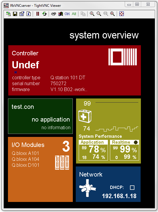
- Clicking on the red section will display all the variables connected to the controller.
- Clicking on the green section will open the test.con program (if one has been created).
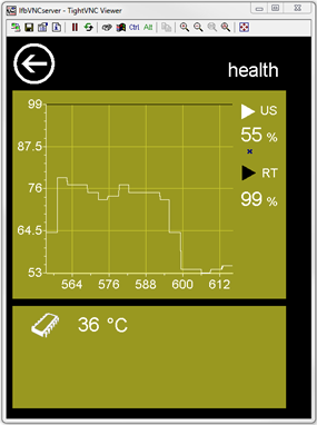
- Clicking on the yellow section will display the overall health of the system.
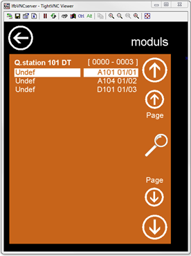
- Clicking on the orange section will display the measurement modules connected to the Q.station, including their UART and address settings.
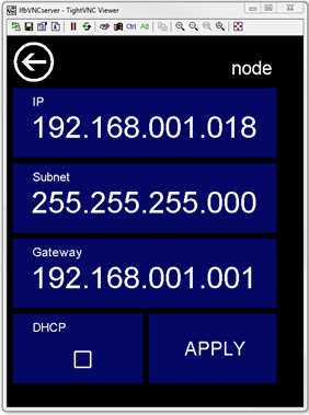
- Clicking on the blue section will display the IP settings of the Q.station, including the static IP, the subnet, the gateway, and DHCP.
- If the Q.station is connected to a wireless router, a VNC viewer application on a mobile device (i.e., cell phone or tablet) can also connect to the Q.station’s VNC screen.