About the Q.series XE
Configuring the Q.series XE modules
Configuring the EtherCAT network
How to generate an ESI file
About the Q.series XE
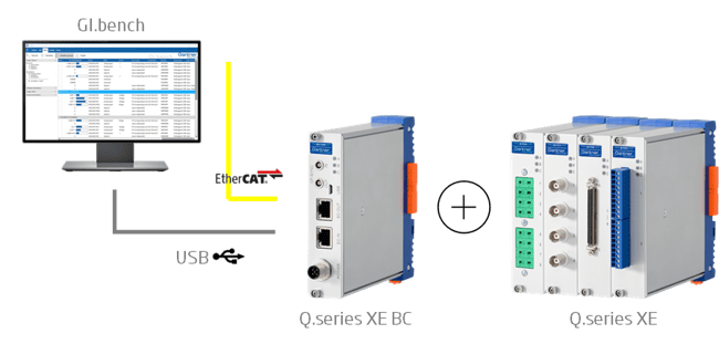
Gantner Instruments offers Q.series XE I/O modules as individual EtherCAT slave devices, combining the precision and performance of Q.series X for EtherCAT applications.
Each module includes an ET1100 EtherCAT slave controller compliant with EtherCAT slave implementation guide with distributed clock support and connects via an LVDS interface to a Q.series XE Bus Coupler.
The Q.series XE modules support EtherCAT cycle times that are integer divisors of 100 kHz (e.g., 1, 2, 4, 5, 10 kHz). They also support oversampling based on Beckhoff’s eXtreme Fast Control (XFC) technology, transmitting up to 100 samples per bus cycle. See also EtherCAT Oversampling with XFC technology.
Configuring the Q.series XE modules
The Q.series XE modules are delivered with a default configuration. As a first step, configure the modules using GI.bench via the Micro USB interface connected to the Bus Coupler.
For frequently used EtherCAT masters, a dedicated interface allows direct import of module configurations into GI.bench for easy (re)configuration. See this article for detailed instructions. Currently supported EtherCAT masters in GI.bench:
Beckhoff TwinCAT | KPA EtherCAT Master | acontis EtherCAT Master Stack
-
Connect a Micro USB cable from the Bus Coupler to the PC.
👉 If no modules are detected, verify that DIP switches 1 and 2 are set to HIGH at the bus coupler. For Q.bloxx XE and Q.brixx XE modules, the DIP switches can be accessed by removing the socket using the screws on the front plate.
-
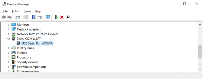
Verify the assigned COM port in Device Manager under Ports (COM & LPT).
-
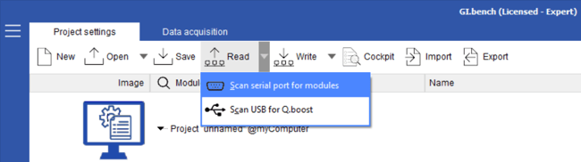
Open GI.bench. It starts with a blank (new) project. Select Read → Scan serial port for modules.
-
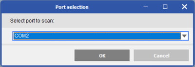
From the pop-up window, select the appropriate COM port.
-
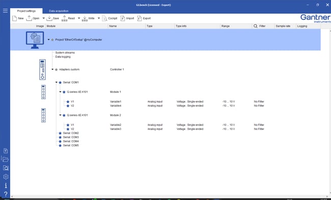
GI.bench will now scan the COM port and list all detected modules, along with the current variable settings stored on each module, under the respective COM port branch.
-
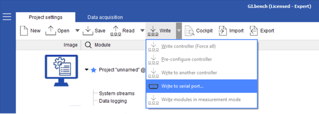
After reconfiguring the modules, the settings can be written back by selecting Write → Write to serial port...
Configuring the EtherCAT network
When configuring slave devices in an EtherCAT master, two key description files are essential: the EtherCAT Slave Information (ESI) file and the EtherCAT Network Information (ENI) file.
-
The ESI file is device-specific and details the process data objects for that device.
-
The ENI file describes the network topology, initialization commands for each device, and cyclically transmitted data.
The EtherCAT master uses the ENI file to initialize and configure the EtherCAT network.
In most cases, the EtherCAT master includes a configuration tool to generate an ENI file using the ESI files provided by Gantner Instruments. Alternatively, the Beckhoff EtherCAT Configuration Tool ET9000 can be used.
Depending on whether the EtherCAT master can scan the network online, there are two ways to provide the ESI files to generate the ENI file:
- EtherCAT master with dynamic PDO mapping capability:
Due to the highly flexible configuration of Q.series XE modules, the PDO mapping can vary, even between modules of the same type. In such cases, most EtherCAT masters must be configured to read the configuration-specific PDO mapping via CAN over EtherCAT (CoE). To support this, Gantner Instruments provides a pre-generated ESI file named Gantner Instruments.xml. This file contains general module information, excluding PDO details, for all Q.series XE modules and includes instructions for online PDO retrieval via CoE. The file is available in the GI.bench user directory:
C:\Users\Public\Documents\Gantner Instruments\GI.bench\additionals\EtherCAT. Alternatively, it can be obtained from your local Gantner Instruments sales and service partner. -
EtherCAT master master without dynamic PDO mapping capability:
If the EtherCAT master lacks support for CAN over EtherCAT, ESI files become essential for static PDO mapping. These files offer additional detailed information about the configuration of the Q.series XE slave device. For instructions on creating an ESI file, please consult the How to generate an ESI File section.
The exported ESI files are tailored to a specific module configuration. If the PDO mapping changes, such as modifications to the number or data type of variables, a new ESI file must be generated for the EtherCAT master.
How to generate an ESI file
For this procedure, GI.bench must be set to Expert mode, which requires either a configuration license or a full license.
-
Connect the modules to the PC via USB cable and read the module configurations as described in section Configuring Q.series XE modules.
-
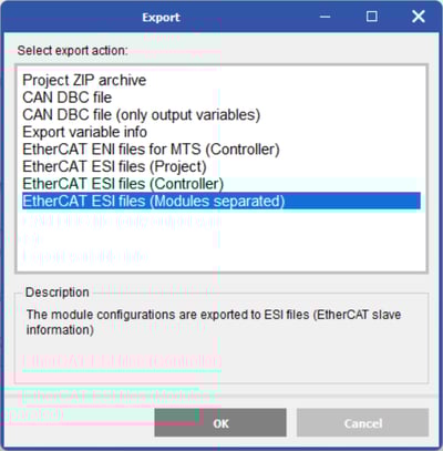
To export the ESI files, select Export → EtherCAT ESI Files (Modules Separated). This option exports a separate ESI file for each module.
-
Next, select the destination folder where the ESI files should be saved. A confirmation message will appear once the files have been successfully generated.

The Bus Coupler cannot be configured and does not contain PDOs, so the same ESI file can always be used.
The ESI files for modules of the same type always share the same product code (e.g., A414 hex, 42004 decimal). The RevisionNo is not used by Gantner Instruments, so it can be modified to differentiate between module configurations in a network configuration tool.