Table of Contents
Minimum computer requirements
- Operating System: Windows XP or later
- RAM: 4 GB or higher
- Processor: Dual Core Processor with a clock speed of 2+ GHz
- Network Connectivity: Ethernet Port
- Peripheral Connectivity: USB Port
- Driver Package: FTDI VCP Driver
Software download and installation procedure
-
Visit the Gantner Instruments website at https://www.gantner-instruments.com/support-downloads/software-downloads/ to acquire the latest version of ICP100.
-
Upon downloading the software package, locate the Setup.exe file.
-
Execute a double-click on the Setup.exe file to launch the installation process. This will prompt the initiation of the Setup Wizard, guiding you through the installation steps.
Software licensing
-
To acquire an ICP100 license, please contact your local Gantner vendor for assistance.
-
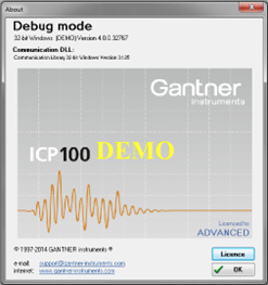
Once within ICP100, navigate to Help > About. In the About window, you'll observe the software operating in DEMO mode. Proceed by clicking the License button located in the bottom right corner.
-
Input the license details into the designated fields, then click OK to validate. Upon successful entry, the software will transition to LICENSED mode.
Establishing connection with a measurement module
Connecting through a controller
This feature is exclusive to Q.station 101 and Q.station X controllers and is currently not available for Q.monixx controllers.
-
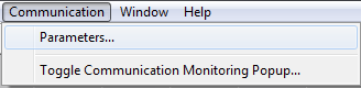
Measurement modules connected to a controller can be accessed via the Ethernet port of the controller. In ICP100, select Communication > Parameters.
-
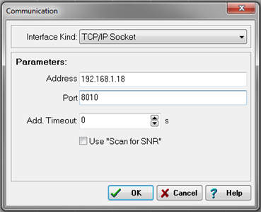
The communication window will appear. In the interface kind drop-down menu, select TCP/IP Socket.
-
Enter the IP address of the controller and the port number of the UART where the module is located. Click OK to apply the settings.
UART # Port # 1 8010 2 8011 3 8012 4 8013 -
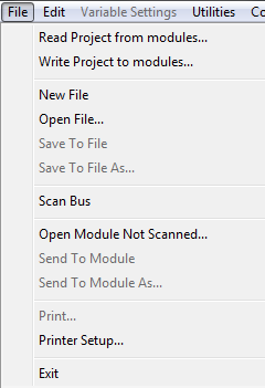
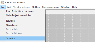
To connect to the attached modules, select File > Scan Bus.
-
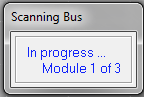
The software will scan the specified UART.
-
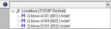
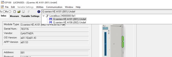
All connected modules will be displayed in the drop-down menu located in the top toolbar.
-
Click on any of the modules to open that module in the workspace.
Connecting through an EtherCAT bus coupler
Sometimes a driver is needed to connect to the Buscoupler via USB.
You can download those drivers from https://ftdichip.com/drivers/
-
Connect a micro-USB cable from the bus coupler to a PC.
-
Verify the COM port of the connection by accessing the Device Manager and checking the Ports (COM & LPT) section.

-
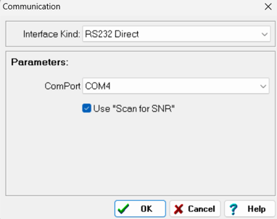
To initiate, open ICP100 and navigate to Communication > Parameters. From the interface drop-down menu, select RS232 Direct and configure the COM port according to the instructions provided in step 2. Additionally, ensure to enable "Use Scan for SNR" option.
-
Go to File > Scan Bus
-
Choose one module at a time from the drop-down list to load the current module configuration.
-
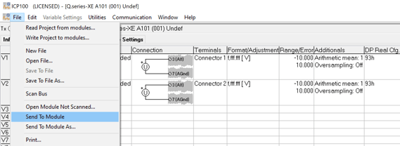
If necessary, configure channels and apply updates by navigating to File > Send to Module.
Direct connection through an USB to RS485 converter
A measurement module can establish a direct connection to a PC through a USB to RS485 converter. For recommended converters, please consult: https://knowledge.gantner-instruments.com/which-serial-converters-and-gateways-can-i-use.
- Verify the COM port of the connection by accessing the Device Manager and checking the Ports (COM & LPT) section.
-
To initiate, open ICP100 and navigate to Communication > Parameters. From the interface drop-down menu, select RS232 Direct and configure the COM port according to the instructions provided in step 2. Additionally, ensure to enable "Use Scan for SNR" option.
- Go to File > Scan Bus
-
Choose one module at a time from the drop-down list to load the current module configuration.
-
If necessary, configure channels and apply updates by navigating to File > Send to Module.
Setting up a measurement module
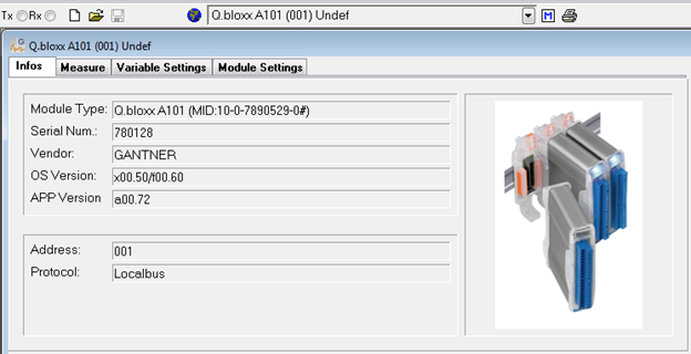
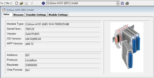
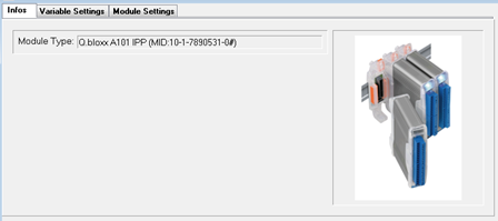
Info tab
The info tab provides specifications about the connected module. This is mainly for diagnostic purposes to ensure the correct module is being modified. The module’s serial number, OS, and APP version are displayed. This is helpful information to provide Gantner technical support personnel with any support calls/inquiries.
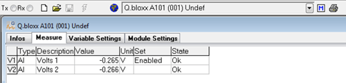
Measure tab
This tab presents real-time data from the configured channels within the connected module. It includes the following details:
- Type: Indicates the nature of the channel, such as analog input, analog output, digital input, digital output, set point, arithmetic, alarm, etc.
- Description: Specifies the name of the channel.
- Value: Displays the current reading from the connected sensor or the displayed value if error checking is enabled.
- Unit: Shows the configured units for the channel.
- State: Indicates the current status or condition of the channel.
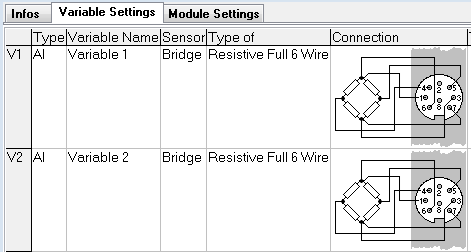
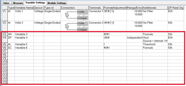
Variable Settings tab
The Variable Settings tab serves as the primary function of ICP100, facilitating channel configuration. Users have access to 16 slots for variables, which can comprise both real and virtual variables.
Physical input channels can be configured on a module depending on its type. The remaining slots can be utilized for virtual variables such as arithmetic, set points, signal conditioning, and alarms. For instance, the A101 module displayed below features 2 channels for universal measurement, leaving 14 slots available for virtual variables.
-
To add a variable, click on the cell where the empty variable row intersects with the Type column. This action will prompt the display of available variable types.
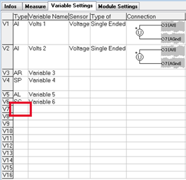
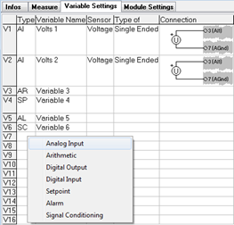
-
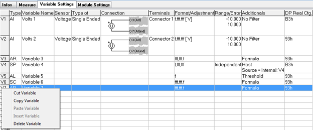
You can perform various actions on variables, such as cut, copy, paste, insert, and delete, by right-clicking on the variable number. This provides an efficient method for organizing, duplicating, and removing variables within a module.
-
Once variables have been added to the table, they can be configured according to specific requirements. The available settings will vary depending on the variable type. Configuration of columns is performed from left to right. To modify the contents, click on the respective cell.
-
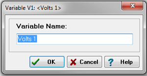
Variable Name: This field provides a unique identifier for the variable. It is imperative that all variables within a project possess distinct names. The variable name can contain a maximum of 20 characters.
-
Sensor: This parameter specifies the type of sensor to be connected to the channel. For instance, if the channel is configured as an analog input on an A101 module, it can be set up for voltage, current, thermocouple (TC), potentiometer, resistance temperature detector (RTD), etc.
-
Type of: This column offers further specifications for the sensor, if applicable. For instance, if a Voltage sensor is chosen, this column can specify whether it is single-ended, differential or IEPE (for an A101 module).
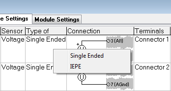
Alternatively, a bridge sensor offers the following selectable types:
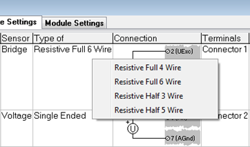
-
Connection: This column illustrates the wiring connection corresponding to the selected sensor type. Note: When utilizing an external special terminal block (e.g., CJC or strain gage bridge completion), refer to the connection diagram provided on the terminal block itself.
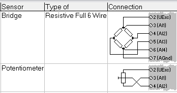
-
Terminals: This column indicates which connector to utilize on the module. Each module typically offers 2 terminals. Connector 1 refers to the top connector, while connector 2 refers to the bottom connector.

-
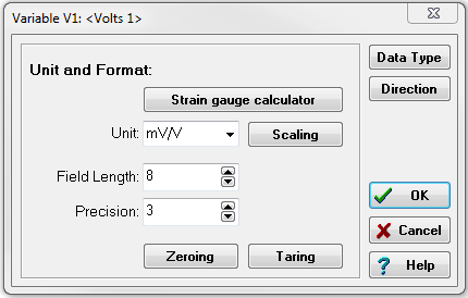
Choose or input the desired units into the designated field.
-
Click on the scaling button.
-
Input the scale factor of the sensor using either a two-point calibration or factor/offset method. In the following example, the conversion is from millivolts per volt (mV/V) to pounds (lbs).
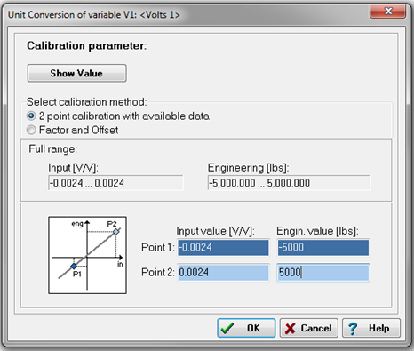
-
Zeroing and/or Taring for this channel can be activated here. Clicking on either option will prompt the display of the following window. Select the method through which the zero and/or tare calibration is initiated.
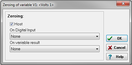
-
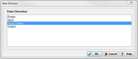
Select the Direction button. To execute zeroing and/or taring for the channel, ensure that Input/Output is chosen as the data direction.
-
Range/Error: This column delineates the expected measurement range of the channel (minimum/maximum). If the sensor or channel detects a measurement outside of this range, an error can be signified by a red LED on the module. To enable this feature, range error checking must be activated.
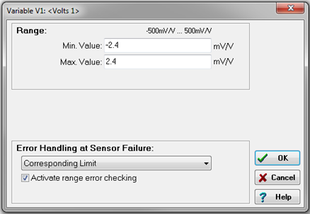
When a range error occurs, the following options are available: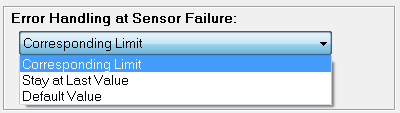
The Error Handling setting defines how the variable behaves in case of a measurement exceeding the defined range:- Corresponding limit: If an error occurs, the variable reading will be set to either the minimum or maximum defined value (+/- 10%), depending on whether the last valid measurement was closer to the minimum or maximum.
- Stay at last value: If an error occurs, the variable reading will remain at the last valid measurement within the defined range (+/- 10%).
- Default value: If an error occurs, the variable reading will be set to a user-defined default value, such as 99999, to indicate an error.
- Format/Adjustment: This column is used to adjust the variable to the relevant engineering unit and set the number format of the variable.
- Additionals: This column enables configuration of any available filters for the channel. These filters may include averaging, lowpass, highpass, and bandpass options.
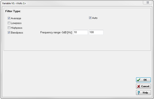
-
-
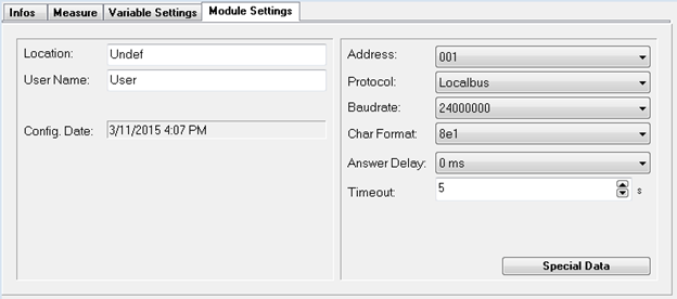
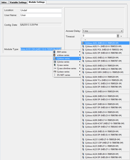
Module Settings tab
This tab is utilized to apply settings to the module, incorporating a comments section for location or user name, the date and time of the module's last configuration, and various communication settings.
Offline configuration mode
The preceding sections detail the configuration process for a module connected to the PC, referred to as "Online" mode. In instances where a module is unavailable, the ICP100 software can operate in "Offline" mode. This mode enables users to review the various settings available on a module and explore potential configurations.
-
To open a specific module, select File > Open File.
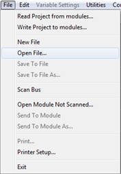
-
A list of modules will be displayed. Choose the file you wish to configure from the list.
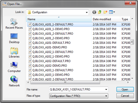
-
In "Offline" mode, the same tabs as those seen in "Online" mode are displayed, with the exception of the Measure tab.
-
Within the Module Settings tab, users can select from various module types for the chosen module, ranging from Q.bloxx and Q.brixx to Q.raxx with special connectors.
-
Once the module type is selected, refer back to the Variable Settings tab for additional details regarding the wiring and pin assignment of the connector.