Introduction
The GInsScanivalvePlugin is a plugin to read data from Scanivalve pressure and temperature measurement equipment via TCP using Telnet port 23. the plugin maps the Scanivalve measuring channels to the virtual variables on a Q.station X controller or Q.core data server such that they can be monitored and logged together with the Gantner Instruments measurement data.
The plugin supports the following Scanivalve module types:
- Scanivalve DTS4050 Digital Temperature Scanner
- DSAENCL4000 Pressure Acquisition System (with DSA3016 pressure scanner modules)
Minimum system requirements
-
Q.station X, Q.raxx station X, or Q.brixx station X controller with firmware v2.15.1 or later
- Q.core 101 or 102 data server with firmware v1.13.1 or later
-
GI.monitor version v1.10.2.0 or later
Plugin installation
Download the correct plugin version that matches the Q.station X or Q.core firmware version from the Gantner Instruments Public Download Area.
For installation instructions please refer to the page: installing a plugin.
Plugin configuration
The configuration of a plugin is done through a plugin-specific configuration interface using GI.monitor.
-
Start GI.monitor from the GI.service UI menu in the system tray (Tools > GI.monitor).
-
To connect to the plugin on a Q.station controller, enter the Server Address
(IP address of your controller), set the Server Port to 1200, and click Connect.
-
To connect to the plugin on a Q.core data server, enter the Server Address
(IP address of your Q.core), set the Server Port to 8090, and click Connect. Enter the administrator username and password. The default username and password is "admin" and "admin".
-
-
Next to the Route dropdown list click Reload and then select /GInsScanivalvePlugin.
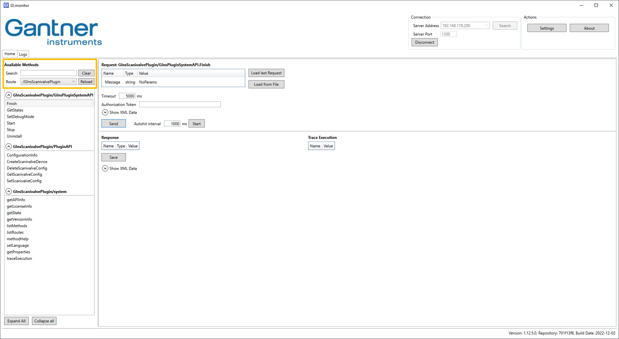
-
Select CreateScanivalveConfig under GInsScanivalvePlugin/PluginAPI. Click Send to add a Scanivalve device to the plugin configuration. To add multiple Scanivalve devices, click Send for every additional device you want to add to the plugin configuration.

-
Select GetScanivalveConfig. From the dropdown list select the Scanivalve device that you want to configure and click Send.

-
Select SetScanivalveConfig to set the device type, IP address, port number, and communication timeout [ms] of your Scanivalve device. Click Send to store the new plugin configuration on the controller. Repeat steps 4 and 5 for each Scanivalve device that you added to the plugin configuration.

If you go to SetScanivalveConfig without selecting a device in GetScanivalveConfig GI.monitor gives an error. To recover, reload the plugin as described in step 2.
All Scanivalve devices that are created in the plugin configuration should be available on the network. If one device is not available, please go to DeleteScanivalveConfig to remove the device(s) that is not available on the network.
Virtual variable configuration
The Scanivalve plugin can write data to the virtual variables on the Q.station X or Q.core. The virtual variables should be configured as Setpoint and the Data direction should be set to Input/Output.
Measurement data
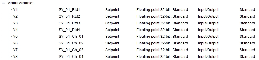
To map the Scanivalve measruement channels to the virtual variables the following naming convention must be followed:
- "SV_0x_Ch_yy", where
-
x = Scanivalve index starting at 1 (continuous count of the Scanivalve modules)
-
yy = Measuring channel 1 - ... (depending on Scanivalve module type)
-
Uniform Temperature Reference (DTS4050 only)
The DTS4050 temperature scanner module has additional Uniform Temperature Reference (UTR) channels that can be mapped to the virtual channels using the following naming convention:
- "SV_0x_Rtdy", where
- x = Scanivalve index starting at 1
-
y = RTD channel 1 - 4
For example:
-
SV_01_Rtd1
-
SV_01_Rtd2
-
SV_01_Ch_1
-
SV_01_Ch_30
Transfer Active
The TransferActive flag provides overall status information. If the plugin cannot connect to any of the devices, no data transfer will be active at all (TransferActive = 0). If it successfully connects to all devices, data transfer will begin (TransferActive = 1).
The same applies if one of the devices disconnects (due to a timeout or error) while data transfer is active. The plugin will revert to the Init state (TransferActive = 0) for all devices and attempt to reconnect to all of them again.