Table of Contents
Requirements
The following are the minimum requirements for generating and using custom MATLAB code plugins:
-
Q.station 101 or Q.station X with firmware version 2.17.0
-
Q.station SDK version 2.17.0
-
GI.bench Data Acquisition Software
-
MATLAB with the Matlab Coder App
-
Capability to run a Docker container on your PC
In this plugin, only MATLAB functions that support C++ code generation are compatible. You can find the complete list of supported functions here.
Software Installation
Installing the MATLAB App
No additional installation is required on the controller itself. Instead, a MATLAB app is needed that contains the user interface. To install the app, navigate to the working directory in MATLAB where the file "GIns Matlab Code Generation.mlappinstall" is located and double-click on it. Then, follow the on-screen instructions to complete the installation.
Installing a Docker Container
Follow the instructions provided by Docker to install Docker on Windows: https://docs.docker.com/desktop/install/windows-install/.
MATLAB App User Interface Overview
The MATLAB app's user interface is designed to be simple and consists of three main sections: General Information, Select Device, and Code Generation.
In the General Information section, setup information is configured, although in most cases, no changes are required. The key aspect here is selecting the correct source folder or current working directory in MATLAB. If this folder is incorrectly set or the necessary setup files are missing, code generation will not be possible. To create a default workspace, use the Generate MATLAB Default Files or Generate Simulink Default Files buttons.
For Simulink models, ensure that the Calculation Rate is set to match the CPU calculation rate of the Q.station being used.
A minimal MATLAB workspace requires the following files:
MatlabFunction_Build.mMatlabFunction_GetInfo.mMatlabFunction_Main.m
For a Simulink workspace, the required file is:
GInsSimulinkMain.slx
In the Select Device section, choose the target device by clicking on its name. You can refresh the device list using the Scan Devices button.
The plugin is generated and built using the buttons in the lower section. You can either build the plugin partially using the buttons on the left or complete the full build process with the Complete MATLAB Process or Complete Simulink Process button on the right.

Plugin Structure
The core of the plugin consists of two MATLAB files that define the desired functionality:
- MatlabFunction_GetInfo.m: Defines the inputs and outputs used in the plugin.
- MatlabFunction_Main.m: Contains the main logic of the plugin.
Additionally, the MatlabFunction_Build.m file is required for code generation, but it doesn't need any modifications.
For Simulink, the necessary information is generated in the GInsSimulinkMain.slx model. This model sets the number of inputs and outputs, along with their descriptions.
A basic template for a controller plugin is provided within the Docker container. This template, along with the C/C++ files generated from MATLAB, is used to compile the final plugin within the container.
MatlabFunction_GetInfo.m
This file defines the interface between the plugin and MATLAB. It uses three key parameters:
-
inputs: Defines the input variables, such as names and descriptions.
-
outputs: Specifies the output variables with corresponding descriptions.
-
debugs: Provides descriptions for debug variables.
Additionally, the Helptext parameter is optional and provides an overview of the function.
The inputs and outputs are exchanged periodically with the CPU clock of the Q.station, while debugs are exchanged asynchronously through the XML-RPC interface.
The file consists of a predefined section and customizable parts for user input. Below is an example of a basic file. As outlined in the Helptext, this function generates two sinusoidal waveforms with noise and filtering.
The interface is structured as follows:
-
inputs: Timestamp, amplitude, and frequency of two sinusoidal waveforms, noise amplitude, and offset.
-
outputs: Ideal signal, signal with noise, and a filtered signal.
-
debugs: Current noise amplitude and two constants for debugging.
Only modify the designated sections of the function! Any changes outside of these areas may prevent the plugin from functioning correctly.
function [InputDesc, OutputDesc, numberInputs, numberOutputs, Helptext, DebugDesc, numberDebugs] = MatlabFunction_GetInfo(InputDesc, OutputDesc, DebugDesc)
%% This is the help for the matlab function
% It returns some helpful description of the inputs/outputs for the
% main functions.

%% How to use
% Just modify the cell arrays inputs, outputs and Helptext

%% Params (don't change!)
% InputDesc: An array containing description for each input
% outputVector: An array containing description for each output
% Helptext: An additional Text for general information

% numberInputs: The number of inputs (=number of rows in InputDesc)
% numberOutputs: The number of outputs (=number of rows in OutputDesc)

%% User Inputs (Change according to your values)
    % Enter the description for each input/output
    inputs = {'Timestamp (ns)','Amplitude 1','Amplitude 2','Frequency 1','Frequency 2','Amplitude Noise', 'DC Offset'};
    outputs = {'Signal without Noise', 'Signal with Noise', 'Signal filtered'};
    debugs = {'Amplitude Noise', 'ConstValue 1', 'ConstValue 2'};

    Helptext = "This function generates two Sinus signals with an additional Noise. The Signal is then filtered using a lowpass filter.";

%% Processing (don't change!)
    MAX_VARIABLE_NAME_LENGTH = 150;

    numberInputs = size(inputs,2);
    numberOutputs = size(outputs,2);
    numberDebugs = size(debugs,2);

    InputDesc = char(zeros(MAX_VARIABLE_NAME_LENGTH, numberInputs));
    OutputDesc = char(zeros(MAX_VARIABLE_NAME_LENGTH, numberOutputs));
    DebugDesc = char(zeros(MAX_VARIABLE_NAME_LENGTH, numberDebugs));

    % Fill in Names
    for idx = 1:numberInputs
        InputDesc(1:length(inputs{idx}),idx) = inputs{idx};
    end

    for idx = 1:numberOutputs
        OutputDesc(1:length(outputs{idx}),idx) = outputs{idx};
    end

    for idx = 1:numberDebugs
        DebugDesc(1:length(debugs{idx}),idx) = debugs{idx};
    end
end
MatlabFunction_Main.m
This file defines the core logic of the plugin. It consists of a predefined section and a section for user-defined logic.
The interface variables specified in MatlabFunction_GetInfo.m (inputs, outputs, and debugs) are represented by the vectors inputVector, outputVector, and debugVector, in the order described.
An example file is provided below, which demonstrates sinusoidal waveform generation. Custom functions, such as MyLowpassFilter.m, can also be used, provided they are compatible with code generation.
Only modify the designated parts of the function! Any other changes may prevent the plugin from functioning correctly (note: vectors in MATLAB start at index 1).
function [returnCode, inputVector, outputVector, debugVector] = MatlabFunction_Main(inputVector, outputVector, debugVector)
%% This is the main matlab function
% This is a small example.

%% How to use
% Change the expected number of inputs/output (inputSize,
% outputSize). The custom logic can be added like the example seen below.

%% Params (don't change!)
% inputVector: A vector containing the input of this function. Passed as
% pointer

% outputVector: A vector containing the result of this function. Passed
% as points

% returncode: Some returncode to give information about success


%% Check if input/output size is big enough (don't change)
    [~, ~, inputSize, outputSize, ~, ~, debugSize] = MatlabFunction_GetInfo();

    if (max(size(inputVector)) ~= inputSize || min(size(inputVector)) ~= 1 || ...
            max(size(outputVector)) ~= outputSize || min(size(outputVector)) ~= 1)
        returnCode = -1;
        return;
    end


%% User Logic (Change according to your needs)
    % Inputs
    currentTime = inputVector(1);       % in ns
    currentTime = currentTime *10^-9;   % in s

    noiseAmplitude = inputVector(6);
    noise = rand*noiseAmplitude*2 - noiseAmplitude;

    dcOffset = inputVector(7);

    currentSignal = MySinus(currentTime, inputVector(2), inputVector(4)) + MySinus(currentTime, inputVector(3), inputVector(5)) + dcOffset;
    noiseSignal = currentSignal + noise;
    filteredSignal = MyLowpassFilter(noiseSignal);

    % Outputs
    outputVector(1) = currentSignal;
    outputVector(2) = noiseSignal;
    outputVector(3) = filteredSignal;

    debugVector(1) = noise;
    debugVector(2) = 1;
    debugVector(3) = 2;

    returnCode = 0;
end
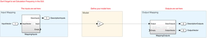
GInsSimulinkMain.slx
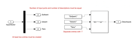
This file defines the Simulink model used for code generation. The mapping of inputs and outputs is handled on the left and right sides, while the middle section serves as a placeholder for the model itself.
In this file the model for Simulink code generation is described. On the left and right side the mapping is done and in the middle there is a placeholder for a model.
Plugin Configuration Guide
The configuration of a MATLAB plugin is done via the plugin web interface or the GI.monitor configuration interface.
-
Controller Virtual Variables
Before configuring the plugin, ensure that the controller's virtual variables are created and set as Setpoint. These virtual variables will be used for communication between the plugin and the controller. -
Assign Variable Mapping via Plugin Webinterface
Use the plugin webinterface to assign the variable mappings:- Navigate to:
http://<Controller_IP>:8090/<Plugin_Name>/index.htm
- Navigate to:
-
Configure via GI.monitor
To configure using GI.monitor, follow these steps:-
Open GI.monitor from the GI.bench menu in the system tray.
-
Enter the controller’s IP address in the Server Address field and set the Server Port to
1200, then click Connect.If you do not know the IP address, use the Search button to find available controllers on your network.
-
Next to the Route dropdown, click Reload and select
/GInsMatlabPlugin. -
Select ConfigureMapping under GInsMatlabPlugin/PluginAPI to map the controller variables with the MATLAB variables. Click Send to save the configuration.
-
-
Debugging
You can also view the current values of debug variables using GetCurrentDebugValues under the GInsMatlabPlugin/PluginAPI section.
Example: Setting Up and Using the MATLAB Plugin with GI.bench
-
Setup Project in GI.bench
-
Create a new project and add your controller.
-
On the controller, create virtual setpoint variables for each variable used in the plugin.
-
-
Build the Plugin
-
Open the MATLAB app.
-
Generate default files for the plugin.
-
In
MatlabFunction_GetInfo.m, set the input, output, and debug variables. Ensure there is at least one entry in each category. -
Implement the desired functionality in
MatlabFunction_Main.m.
-
-
Generate and Install the Plugin
-
In the MATLAB app, select the desired Q.station and verify the working directory and path to the WebSocket utility.
-
Start the code generation process using the appropriate buttons. Once completed, install the plugin on the Q.station.
-
-
Apply Variable Mapping
-
Connect to the Q.station using GI.monitor.
-
Navigate to the plugin and set the variable mapping under Configure.
-
-
Show Results
- Return to GI.bench.
- Add a YT-chart, for example.
- Drag the output variables into the chart to visualize the results.
This example outlines the steps to set up, build, and apply a MATLAB plugin with GI.bench for effective data visualization and analysis.
Manual Installation
Introduction
This section provides the steps for manually using the plugin, which might be necessary if Docker cannot be used on Windows, for example.
Requirements
-
PC with MATLAB and the MATLAB App installed and an internet connection.
-
PC with Docker installed and an internet connection.
-
PC with GI.bench installed for plugin installation on the device.
Tutorial Setup
-
Main PC: Windows 10 with MATLAB R2021b and GI.bench V1.14.4.
-
Build PC: Debian 10 with Docker.
Build Docker Container
-
Open the MATLAB App in MATLAB and navigate to the working directory.
-
Click the Build Docker Container button. This will generate a subdirectory called docker/ containing a dockerfile and an SDK for compilation (replace the SDK if needed with the matching version.)
-
Copy the directory to the system with Docker installed. Ensure the SDK is marked as executable.
-
Run the build command specified in
BuildContainer.bat:docker build -t gins_matlab_container.
Generate MATLAB Code
-
In the MATLAB App, generate the default files and modify functionality as needed.
-
In the app's Advanced Options ribbon, use the Generate Source Code button to start code generation. MATLAB and its toolboxes are required for this step.
Compile Plugin
-
Copy the entire Sources/ folder (including
MatlabSourceCode.zip) to the build system. -
Run the build container with the following command (adjust options as needed):
docker run --rm -v "/home/user1/Downloads/MATLAB/Sources/":/GInsPluginWork/ gins_matlab_container ./opt/GInsContainerTemplates/StartUp.sh -n "GInsMatlabPlugin" -t "Matlab Plugin" -d 175 -v 2.17.0 -a V3-32 -m-n: Name of the plugin (refer toMatlabFunction_GetPluginDescription.m)-t: Title of the plugin (refer toMatlabFunction_GetPluginDescription.m)-d: Device ID (use175for Q.station) - no change needed-v: Version of SDK (forgins-qstation-sdk-toolchain-2.17.0.919.sh, use2.17.0and omit the last build number)-a: Firmware architecture (useV3-32for 32-bit) - no change needed-m/s: Use-mfor MATLAB and-sfor Simulink
-
Rename
Sources/GInsMatlabPlugin_usb_install.ziptoGInsMatlabPlugin_##qstation-x32_2.17.0.999999.zip(use your plugin name from the-noption and the SDK version from-v).
Install Plugin
The final GInsMatlabPlugin_##qstation-x32_2.17.0.999999.zip can now be installed on the Q.station. Refer to this knowledge base article for instructions.