1. Minimum System Requirements
3. General Station Description File
1. Minimum System Requirements
-
Q.station X PN, Q.brixx X station PN, or Q.raxx X station PN.
-
GI.monitor version 1.10.2.0 or later, which is included with the GI.bench installation. the latest version of GI.bench can be downloaded here.
2. Plugin Installation
Download the correct plugin version that matches the controller firmware version from the Gantner public download area. The plugin version must match the version of the controller firmware.
For installation instructions please refer to the page: installing a plugin.
When ordering a Q.station X controller with the PROFINET add-on module, the plugin is pre-installed at the factory.
4. Plugin Operating Theory
The process image variables in the Q.station controller are transferred using slots and subslots. There are two types of subslots:
-
Input subslot: Transfers input data from the PROFINET IO device to the PROFINET IO controller.
-
Output subslot: Transfers output data from the PROFINET IO controller to the PROFINET IO device.
Subslots are organized within slots:
-
Input subslots are grouped in Input slots.
-
Output subslots are grouped in Output slots.
A process image variable is assigned to subslots based on its data direction:
-
Input subslot: A process image variable with INPUT or INPUT/OUTPUT data direction can be assigned here. Its input value is read and sent to the PROFINET IO controller.
-
Output subslot: A process image variable with OUTPUT or INPUT/OUTPUT data direction can be assigned here. The value sent by the PROFINET IO controller is written to the process image variable’s output.
-
Both Input & Output slots: A process image variable with INPUT/OUTPUT data direction can be assigned to both an Input and an Output slot. This allows, for example, the transfer of a controller setpoint variable to the PROFINET IO controller while also enabling the PROFINET IO controller to modify its value.
The data type of a subslot is automatically determined by the data type of the assigned process image variable, implicit data conversion is not supported. For example, a process image variable with the data type SInt32 will automatically configure a subslot with the data type Integer32.
The actual process data image (separately for input and output data) is determined by the order of the slots (slot number) and the sequence of variables assigned to the subslots (subslot number).
The size of the process data image, separately for input and output data, depends on the number and data type of the subslots.
The maximum size of the process data image is 1440 bytes: a maximum of 1440 bytes for input data and 1440 bytes for output data. This includes:
-
The size of the IO Consumer Status and IO Provider Status, which are counted toward the maximum size.
-
The maximum size of 1440 bytes also includes 4 bytes for the interface (Data Access Point and ports).
Process Data Image for Input Data:
-
4 bytes for Provider Status (interface: Data Access Point and ports)
-
Process Data: The required number of bytes for each Input Subslot (1–8 bytes)
-
Provider Status: 1 byte for each Input Subslot
-
Consumer Status: 1 byte for each Output Subslot
Process Data Image for Output Data:
-
4 bytes for Consumer Status (interface: Data Access Point and ports)
-
Consumer Status: 1 byte for each Input Subslot
-
Process Data: The required number of bytes for each "Output Subslot" (1–8 bytes)
-
Provider Status: 1 byte for each Output Subslot
Example: Only input data, with no output data, is transferred. A maximum of 287 variables with the 32-bit Float data type can be transferred.
5. Plugin Configuration
Activate Controller Plugin Mode
Before configuring the plugin, activate plugin support in the controller settings using GI.bench (Edit controller > Settings > Plugin mode).

Configure the Plugin with GI.monitor
The configuration of a plugin is done through a plugin-specific configuration interface using GI.monitor.
-
Start GI.monitor from the GI.service UI menu in the system tray (Tools > GI.monitor).
-
To connect to the plugin on a Q.station controller, enter the Server Address (IP address of your controller), set the Server Port to 1200, and click Connect.

-
Next to the Route dropdown list click Reload and then select /GInsPNIODevice.
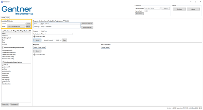
Under GInsPNIODevice/GInsPluginSystemAPI, the general methods (API calls) for the plugin management system are displayed. Under GInsPNIODevice/PluginAPI, the available methods specific to the PROFINET IO plugin are listed.
To action a method, use the Send command in the Request pane on the right.
- Using the Configure method, the functionality of the plugin is configured for PROFINET IO device. Any changes to the configuration take effect only after the Stop method has been executed and then the Start method is called. The configuration is saved permanently in an XML file located in the plugin's installation directory.
- If no configuration file is available when the plugin is started, a configuration for the PROFINET IO device is automatically created from all PI variables available in the controller and saved. This default configuration can then be edited using the Configure method in GI.monitor. By calling the ConfigureDefault method, a new default configuration can be created at any time.
When the plugin is removed or reinstalled, the existing configuration file is deleted, and the saved configuration is lost.
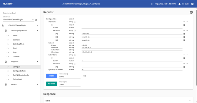
Method: Configure
Slots and subslots
Each slot must be assigned a unique slot number (SlotNr = 1 - 255). Subslots can be assigned to each slot by specifying variable names. The order of the subslots and their subslot numbers (1 - 255) is determined by the order of the variables. The data type of the subslot is automatically determined based on the data type of the variable.If an input slot is assigned a variable that does not have the data direction INPUT or INPUT/OUTPUT, the variable is ignored during configuration, and no input subslot is created for it. Similarly, if a variable is assigned to an output slot that does not have the data direction INPUT or INPUT/OUTPUT, the variable is ignored during configuration, and no output subslot is created for it.
Network
- Gateway: The specification of the IP address for the gateway is optional. If no IP address is explicitly assigned, it is indicated as "0.0.0.0".
-
IPAddress: The specification of the IP address for the Q.station PROFINET IO device is optional. If no IP address is explicitly assigned, it is indicated as "0.0.0.0". In this case, the IP address for the PROFINET IO device is assigned by the PROFINET IO controller.
-
StationName: The specification of the station name is optional. If no name is assigned to the station (empty field), the station name is automatically generated as: “qstation-<serial number>” (example: qstation-770849). If a name is assigned to the station, the following rules must be observed:
-
-
1 or more labels, separated by a full stop (.)
-
Total length: 240 characters.
-
Label length: 63 characters.
-
Labels can only contain (a-z), (0-9), and (-).
-
Labels cannot start or end with (-).
-
Labels cannot contain multiple consecutive (-).
-
The first label cannot have the form “port-xyz” or “port-xyz-abcde” where a, b, c, d, e, x, y, z = 0-9, to avoid confusion with the field AliasName.
-
Station names cannot have the form a.b.c.d, where a, b, c, d = 0-999.
-
-
SubnetMask: The specification of the IP address for the subnet mask is optional. If no IP address is explicitly assigned, it is indicated as "0.0.0.0".
SystemCycleCounter
The system cycle counter specifies that the cycle time for updating the I/O data is either equal to or a multiple of the Q.station's system sample rate, with a minimum of 1 ms (1 kHz).
By setting the system cycle counter to a value greater than 1, the cycle time for updating the I/O data is reduced. The cycle time is then calculated as: System Cycle Counter * System Sample Rate.
Compliance with a cycle time < 10 ms (>100 Hz) depends on the following conditions:
-
The CPU load of the Q.station controller, influenced by factors such as data transfer between the controller and PC, data logging, and the number of active plugins.
-
The stability of the time signal used for time synchronization.
It is strongly recommended to verify that the cycle time for updating the I/O data is maintained after every configuration change.
Method: ConfigureDefault
With this method, a configuration for the PROFINET IO device is automatically generated from all PI variables available in the controller and saved. This default configuration can be modified using the Configure method in GI.monitor. Calling the ConfigureDefault method creates a new default configuration at any time.
Other default settings:
-
Gateway: 0.0.0.0
-
IPAddress: 0.0.0.0
-
StationName: Empty (automatically generated)
-
SubnetMask: 0.0.0.0
-
SystemCycleCounter: 10 ms
Method: GetPNIODeviceConfig
The GetPNIODeviceConfig method retrieves the current configuration and operating status. The PROFINET IO controller is configured based on this information and the Q.station's device description file (GSDML file).
The actual configuration may differ from the one set using the Configure method, for example:
- Variables with an incorrect data direction.
- A SystemCycleCounter value that results in an IOCycleTime below the minimum permissible limit.
IOCycleTime and SystemCycleTime parameters are specified in microseconds (µs).
Method: SetLogLevel
Entries are written to the log file based on the set LogLevel. The LogLevel can be changed using the plugin method SetLogLevel. Available values are: Log level none, Log level error, and Log level information.
When the plugin is started, a log file named ginspniodevice.log is created if the LogLevel is not set to Log level none. If the LogLevel is changed to a value other than Log level none after the plugin has started, the log file will be created automatically, provided it does not already exist.
The log file can be read and edited (e.g., clearing its contents) via an FTP connection (user: "6", password: "6"). The log file is located in the /tmp/gins_tmp/ directory.
The SetLogLevel setting is not saved in the plugin configuration file.
The log file should not be deleted. If the plugin is removed or reinstalled, the existing log file will be deleted, and its data will be lost.
The log file is stored in a temporary RAM directory and is deleted when the controller is powered off.
As the storage space is limited, the log file should not take up too much space to avoid affecting other processes.
Example of a log file (the timestamp before each entry is in UTC):
[12.12.2019 10:25:28] PluginInit(): begin
[12.12.2019 10:25:28]   Plugin information
[12.12.2019 10:25:28]     Plugin executable: GInsPNIODevice
[12.12.2019 10:25:28]     Plugin main thread name: "PNIOPluginMain"
[12.12.2019 10:25:28]     Plugin version: 0.1 (Dec 12 2019 10:24:01 UTC)
[12.12.2019 10:25:28]     Logging file name: /tmp/gins_tmp/ginspniodevice.log
[12.12.2019 10:25:28]     Logging level: information
[12.12.2019 10:25:28]     GLIBC version: 2.26
[12.12.2019 10:25:28]     Temporary files directory: /tmp/gins_tmp
[12.12.2019 10:25:28] PluginInit(): end
[12.12.2019 10:25:28] PluginMain(): begin
[12.12.2019 10:25:28]   Process information
[12.12.2019 10:25:28]     PID = 928
[12.12.2019 10:25:28]     PPID = 741
[12.12.2019 10:25:28]     Main thread ID = 928
[12.12.2019 10:25:28]   PluginMain(): SMState_NotDefined --> SMState_Init
[12.12.2019 10:25:28]   SMHandler_Init(): begin
[12.12.2019 10:25:28]   SMHandler_Init(): end
[12.12.2019 10:25:28]   PluginMain(): SMState_Init --> SMState_Idle
[12.12.2019 10:25:32]   ==> PluginStart()
[12.12.2019 10:25:32]   PluginMain(): SMState_Idle --> SMState_Start
[12.12.2019 10:25:32]   SMHandler_Start(): begin
[12.12.2019 10:25:32]     Starting PNIODevice ...
[12.12.2019 10:25:32]       Load plugin configuration ...
[12.12.2019 10:25:32]         PNIODevice: set thread real-time scheduling ...
[12.12.2019 10:25:32]           PNIODevice: real-time scheduling, policy = SCHED_RR, priority = 90
[12.12.2019 10:25:32]         PNIODevice: Thread ID = 7
[12.12.2019 10:25:34]         Driver information
[12.12.2019 10:25:34]           DriverVersion : "cifX Toolkit 1.2.0.0"
[12.12.2019 10:25:34]           BoardCnt      : 1
[12.12.2019 10:25:34]         Board information for board 0
[12.12.2019 10:25:34]           BoardName    : "cifX0"
[12.12.2019 10:25:34]           BoardAlias   : "MyAlias"
[12.12.2019 10:25:34]           BoardID      : 0
[12.12.2019 10:25:34]           SystemError  : 0x00000000
[12.12.2019 10:25:34]           IrqNumber    : 0
[12.12.2019 10:25:34]           IrqEnabled   : 1
[12.12.2019 10:25:34]           ChannelCnt   : 2
[12.12.2019 10:25:34]           DpmTotalSize : 65536[Byte]
[12.12.2019 10:25:34]         System device information
[12.12.2019 10:25:34]           abCookie         : netX
[12.12.2019 10:25:34]           DpmTotalSize     : 32000[Byte]
[12.12.2019 10:25:34]           DeviceNumber     : 1291109
[12.12.2019 10:25:34]           SerialNumber     : 20119
[12.12.2019 10:25:34]           ausHwOptions[0]  : 0x0080 (ETHERNET, internal PHY)
[12.12.2019 10:25:34]           ausHwOptions[1]  : 0x0080 (ETHERNET, internal PHY)
[12.12.2019 10:25:34]           ausHwOptions[2]  : 0xfffb (I2C PIO INTERFACE)
[12.12.2019 10:25:34]           ausHwOptions[3]  : 0xfff6 (SYNC INTERFACE)
[12.12.2019 10:25:34]           Manufacturer     : 1 (Hilscher GmbH)
[12.12.2019 10:25:34]           ProductionDate   : 2019/KW34
[12.12.2019 10:25:34]           ulLicenseFlags1  : 0x00000000
[12.12.2019 10:25:34]           ulLicenseFlags2  : 0x00000000
[12.12.2019 10:25:34]           NetxLicenseID    : 0
[12.12.2019 10:25:34]           NetxLicenseFlags : 0x0000
[12.12.2019 10:25:34]           DeviceClass      : 0x0003 (CIFIX, all PCI types)
[12.12.2019 10:25:34]           HwRevision       : 1
[12.12.2019 10:25:34]           HwCompatibility  : 0
[12.12.2019 10:25:34]         Channel information for channel 0
[12.12.2019 10:25:34]           BoardName      : "cifX0"
[12.12.2019 10:25:34]           DeviceNumber   : 1291109
[12.12.2019 10:25:34]           SerialNumber   : 20119
[12.12.2019 10:25:34]           FWName         : "PROFINET IO Device"
[12.12.2019 10:25:34]           FWVersion      : 3.13.2 Build 0
[12.12.2019 10:25:34]           FWDate         : 17.10.2018
[12.12.2019 10:25:34]           ChannelError   : 0xC0000145
[12.12.2019 10:25:34]           MailboxSize    : 1596[Byte]
[12.12.2019 10:25:34]           IOInAreaCnt    : 2
[12.12.2019 10:25:34]           IOOutAreaCnt   : 2
[12.12.2019 10:25:34]           NetxFlags      : 0x00000032
[12.12.2019 10:25:34]           HostFlags      : 0x00000030
[12.12.2019 10:25:34]           HostCOSFlags   : 0x00000000
[12.12.2019 10:25:34]           DeviceCOSFlags : 0x00000001
[12.12.2019 10:25:34]         Starting controller interface ...
...
Monitoring Cycle Time
The cycle time for IO data exchange is monitored and logged if the Log Level setting is not set to Log level none. Monitoring is performed by evaluating the V1: Timestamp controller variable. The timestamp variable must represent the time since the beginning of the year 2000 in nanoseconds, which is the default time format setting for the Q.station controller.
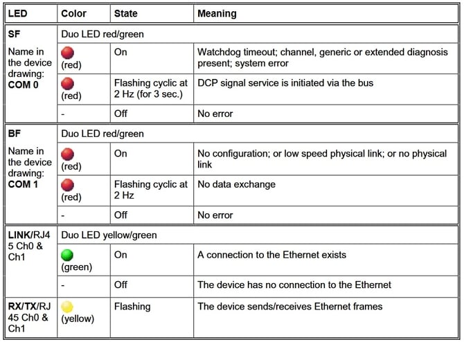
6. Status LEDs

The status LEDs SF (System Error) and BF (Bus Error), as well as the LINK and “RX/TX” LEDs, indicate the following states:
7. Technical Specifications
General specifications
✅ PROFINET IO device
- Vendor ID: 0x04A2 (1186)
- Device ID: 0x00AF (175)
✅ PROFINET specification: V2.3 Edition 2, maintenance update 3 (Ed2 MU3)
Functions and protocols
✅ Cyclic Data Exchange (RT)
❌ Isochronous Data Exchange (IRT)
✅ Acyclic Parameter Data (Record Data CR)
✅ Device Identification(I&M0)
✅ Advanced Device Identification (I&M1-5)
❌ Device Diagnostics
❌ Alarms
✅ Topology information (LLDP)
✅ Simple Network Management Protocol (SNMP)
✅ Discovery and Basic Configuration Protocol (DCP)
✅ Link Layer Discovery Protocol (LLDP)
❌ Dynamic Host Configuration Protocol (DHCP)
✅ Media Redundancy Protocol (MRP)
❌ Shared Input
❌ Shared Device
❌ Dynamic Reconfiguration (CiR)
❌ System Redundancy (SR-AR)
Cyclical Data Exchange
-
Number of cyclic input data: 1440 bytes max.
(including IO Provider State and IO Consumer State) -
Number of cyclical output data: 1440 bytes max.
(including IO Provider State and IO Consumer State) -
Number of sub-modules: 255 max. (slot 1 - 255)
-
Number of Application Relationships (AR): 1
-
Number of Communication Relationship (CR): 1x Input-CR and 1x Output-CR
-
Cycle time for updating the IO data:
-
minimum 1 ms. (under certain conditions, to be observed)
-
maximum 1 s.
-
Physical Interface
-
Ethernet controller with 2 integrated switch ports
-
Connection: 2x RJ45 jack (IP20)
-
Ethernet 100 Mbit/s
-
Transmission medium: copper cable
-
✅ Full duplex
-
❌ Half-Duplex
-
✅ Auto Negotiation
-
✅ Auto Crossover
The Q.station X controller, as a PROFINET IO device, is not yet certified according to DIN ISO 9001-accredited test reports and should not be used in critical production systems without prior consultation.