
Setting up a Modbus RTU device in a Q.station or Q.monixx
Q.station Modbus RTU setup
As the controller lacks an integrated Modbus RTU interface, a USB-to-Serial converter needs to be employed (such as Gantner Instruments ISK103 for laboratory application or ICP DAS for field application). To achieve this, access the controller settings and navigate to the USB devices section. Configure the Device count as 1 (or higher if multiple USB-to-Serial converters are utilized):

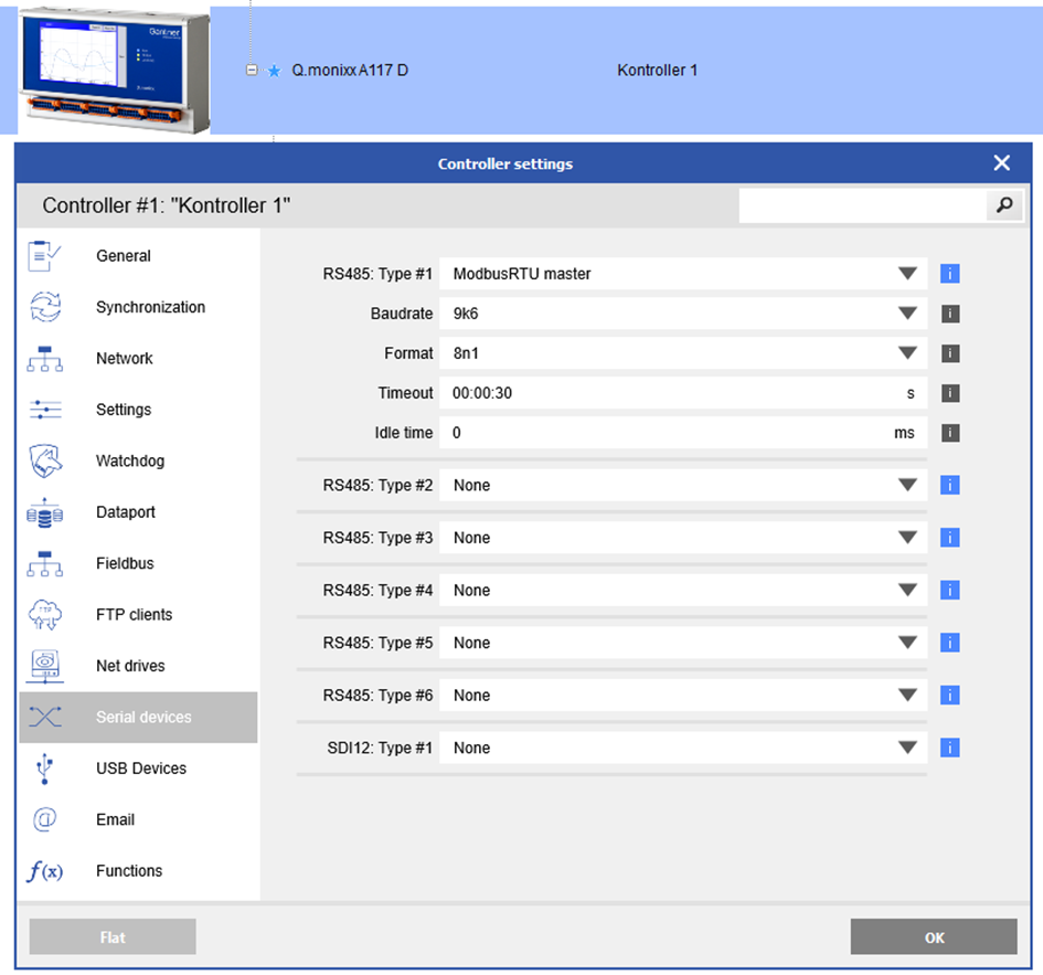
Then the basic parameters of the Modbus RTU communication are defined. For the Sisgeo sensors, the settings are shown in the picture above.
Q.monixx Modbus RTU setup
In contrast to the Q.station, the Q.monixx is equipped with six integrated Modbus RTU interfaces. Access the settings of the Q.monixx and configure the settings for the specific interface under the >Serial devices section. The image illustrates the configuration for the Sisgeo sensor:
Use remote variables for each Modbus signal (Q.station/Q.monixx)
The required remote virtual variables can be created by right-clicking on Controller > Virtual variables via >Add > Append variables:
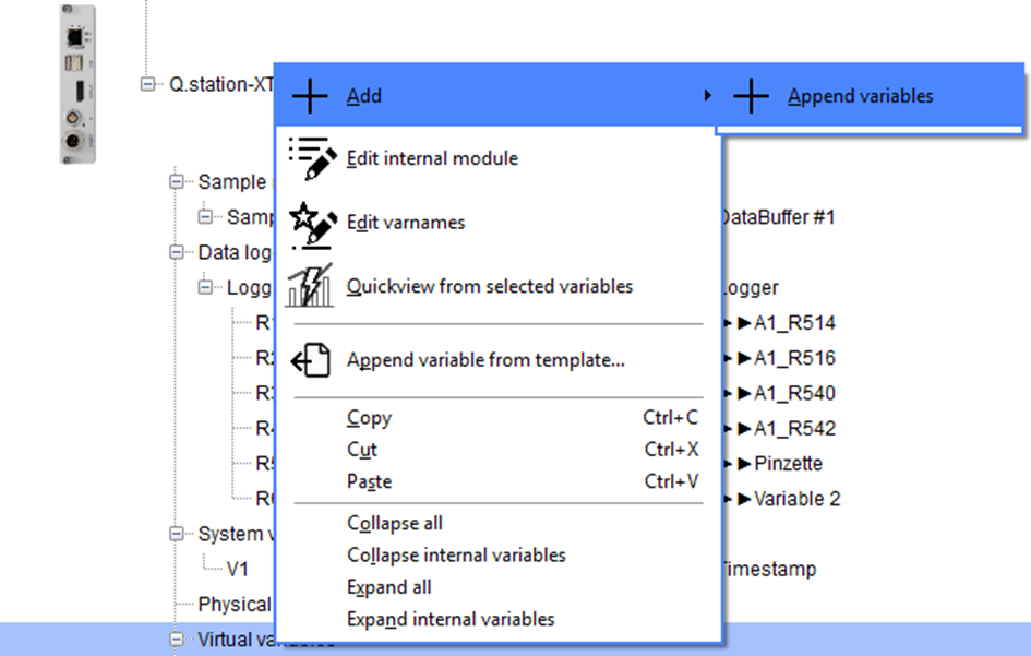
It's advisable to begin with a variable. Later, you can generate multiple variables all at once and edit them concurrently. Another option is to select/copy one or more variables and then paste them beneath the virtual variables. In the majority of instances, only the register and the address need to be edited.
This is an example configuration for a remote virtual variable:

The sensor registers are outlined in hexadecimal format within the Sisgeo manufacturer's manual. For GI.bench, it's necessary to convert these hexadecimal values into decimal values. In this instance, 0x202 equals 514.
Subsequently, these Modbus variables can be handled in GI.bench just like all the other variables.