Setpoints for a digital or analog output can be generated using a controller virtual variable, test.con, or a value from the module itself or from another module.
Using a controller virtual variable
-
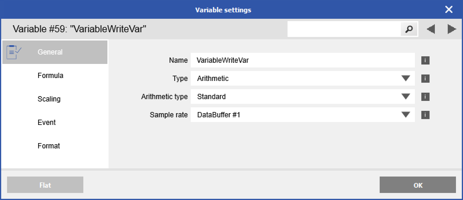
Create a new virtual variable by right-clicking on Virtual Variables > Add > Append Variables. Double-click on the new variable to open the variable settings. In the General tab, change the type to Arithmetic.
-
In the Formula tab, add the VariableWriteIndexBased function to the formula field.
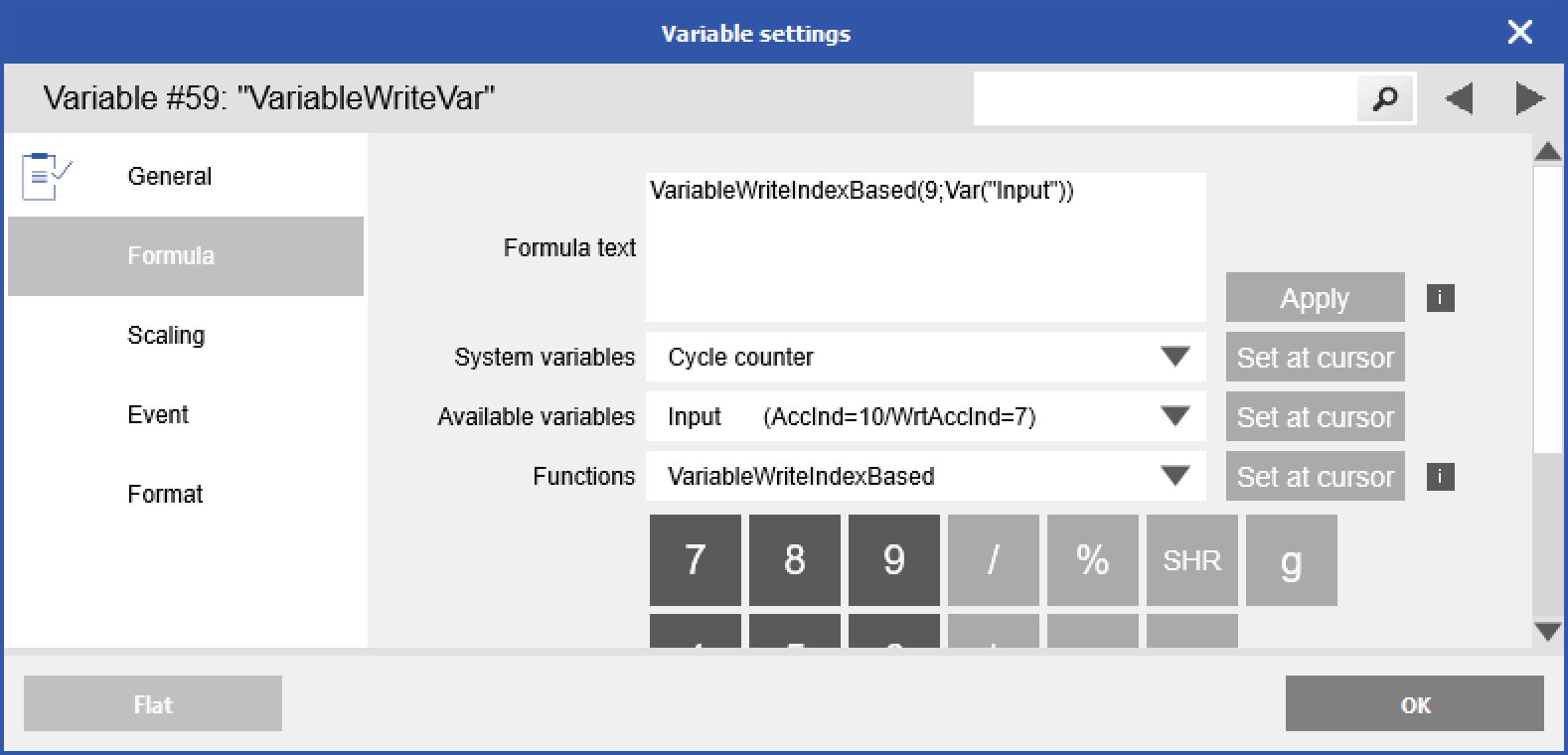
VariableWriteIndexBased(DestinationVariableWriteAccessIndex+1;SourceValue)
-
DestinationVariableWriteAccessIndex+1: Access the index of the output variable where the source value will be written. Only variables with an output data direction (OUTPUT or INPUT/OUTPUT) are allowed. IMPORTANT: Increment the Write Access Index number ("WrtAccInd") as shown in GI.bench by 1 .
-
SourceValue: The variable where the value comes from.
Example Setup:Variable
Data Direction
WrtAccInd
V1 - Timestamp
INPUT
V2 - Setpoint1
INPUT
V3 - Setpoint2
INPUT/OUTPUT
0
V4 - Setpoint3
INPUT
V5 - Setpoint4
OUTPUT
1
V6 - VariableWriteVar
INPUT
V7 - SourceValue
INPUT/OUTPUT
2
Example 1: VariableWriteIndexBased(1;Var(“V7 - SourceValue”))
👉 Value of “V7 - SourceValue” is written to “V3 - Setpoint2”.
Example 2: VariableWriteIndexBased(2;Var(“V7 - SourceValue”))
👉 Value of “V7 - SourceValue” is written to “V5 - Setpoint4”.
-
- Click Apply to set formula, then OK to save changes to the virtual variable
- Write updates to controller.
Now when you change the source variable's value, it will be written to the defined output variable.
Using test.con
In a test.con project, input variables can be connected to output variables to transfer their values.
-
Run the test.con software and create a new userspace or real-time project.
-
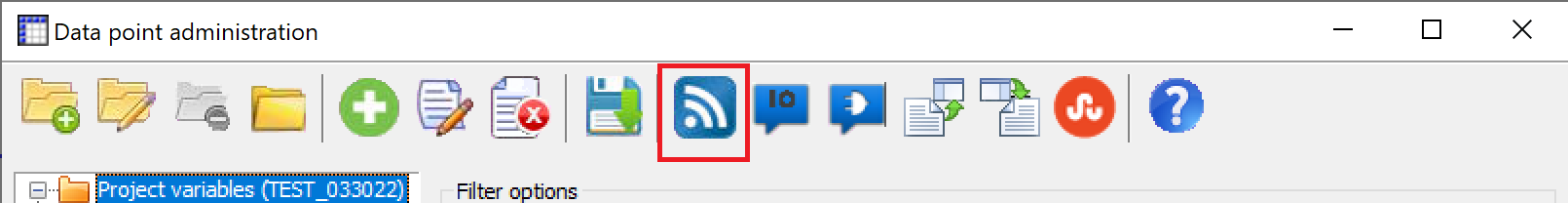
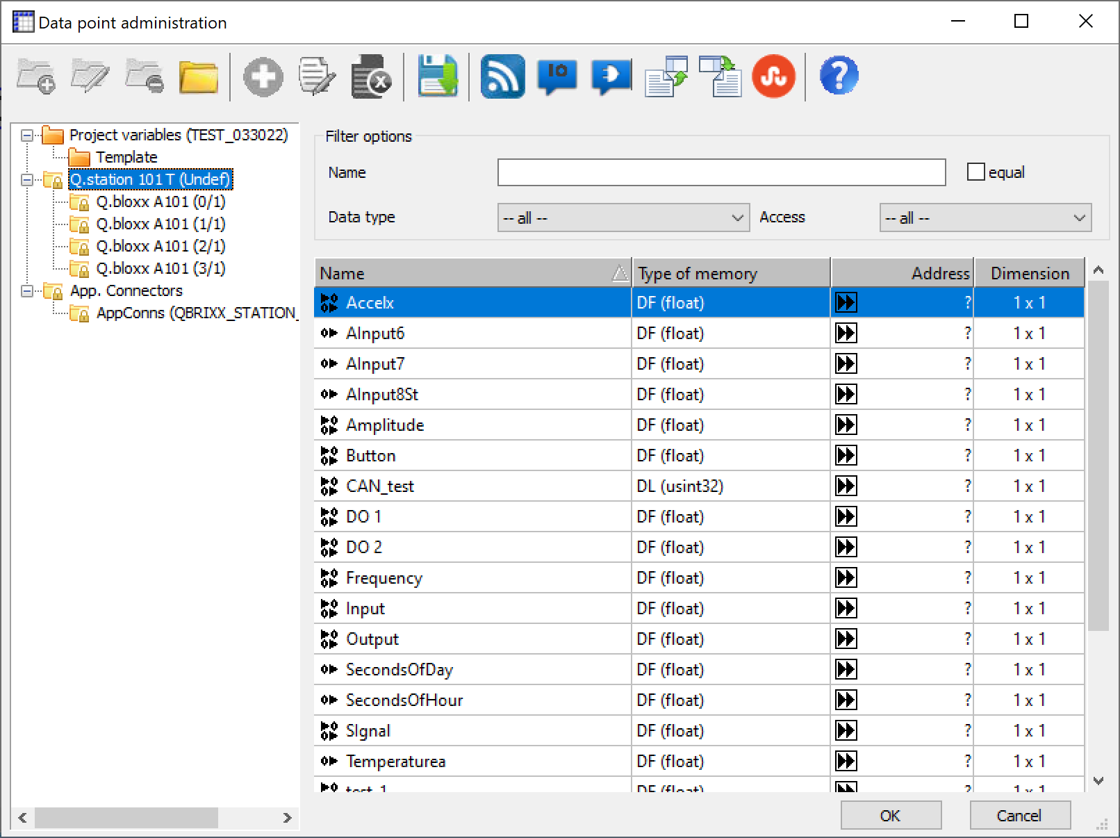
Go to Tools > Data Point Administration.
-
Click Online Import Configuration.
-
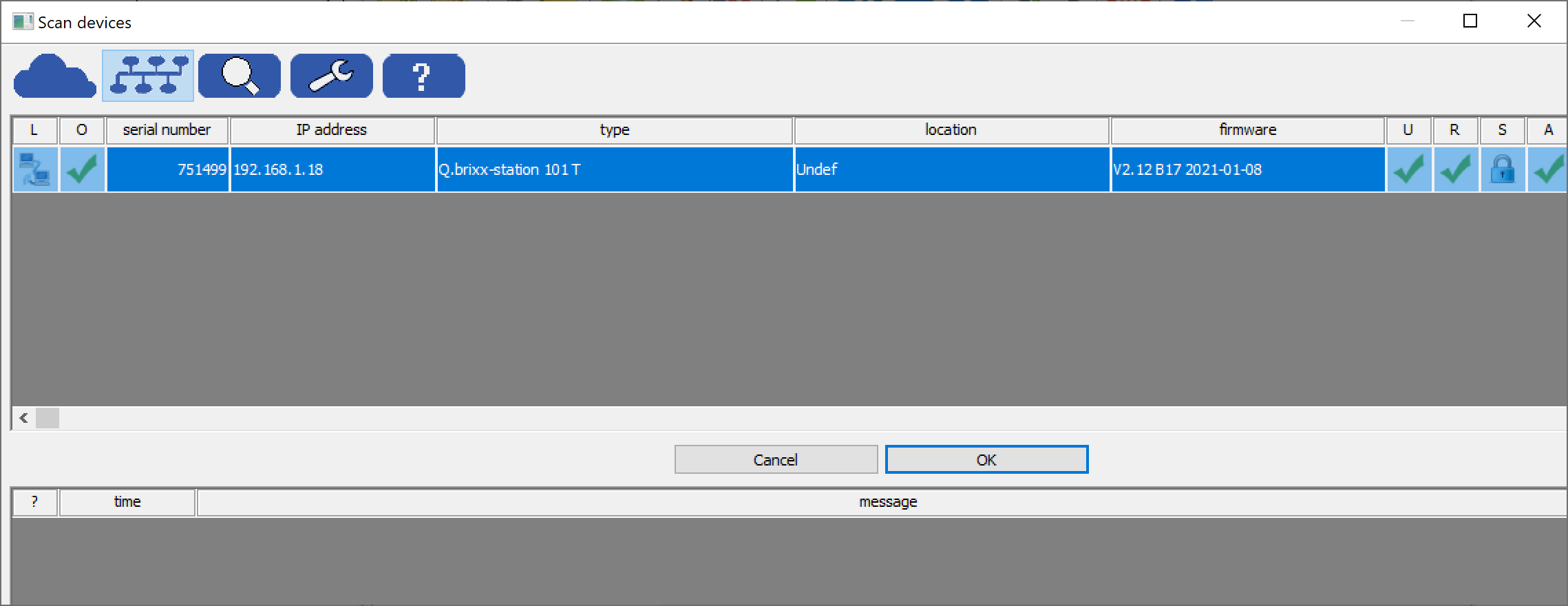
Scan for the connected controller. Once found, select it and click OK.
-
The variables configured in the controller and modules will be loaded into the Data point administration window. Variables configured within the controller can be seen by highlighting the controller in the tree. Click OK to close window.
-
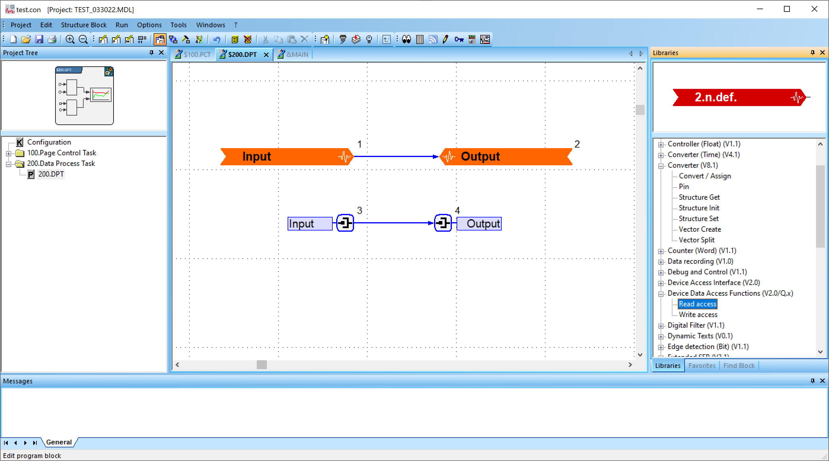
In a program or macro block, you can drag functions block from the libraries section on the right.
-
Device Data Access Functions > Read/Write access
When dragged into the window, it will prompt you to select a corresponding input/output variable to read from/write to. Connect a line between the read and write blocks or add additional function blocks in between. -
Converter > Pin
Provides a pin where you can assign a parameter or variable. Right-click the pin and select Assign Variable, select the corresponding input/output variable. Connect a line between the read and write blocks or add additional function blocks in between.If you don't see the library you need, make sure it is loaded by going to Project > Load Library. Select libraries needed and click Load.
-
-
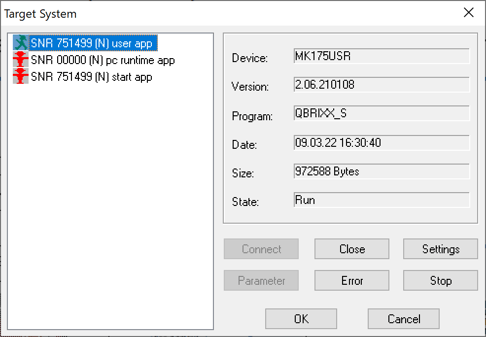
Go to Run > Download. It not done yet, it will prompt you to login to the target system. Select the appropriate user or realtime app and click Connect. Click OK to proceed.
-
Once logged in it will download the program into the controller.
Using values from the same module
Some modules, such as the A106, A109, D101, and A192, have both input and output channels. In these cases, inputs can be routed directly to outputs without using the controller or UART. Each module writes variable data into assigned time slots to ensure deterministic data transfer, and modules can be configured to read this time slot data directly from other modules.
The order of module addresses on the UART is important for this feature to function correctly. Ensure that source modules are assigned lower addresses than the modules reading the data.
Example: Sending data from the strain gage bridge input of the A106 module directly to the Analog Output of the same module:
Analog input configuration

Analog output configuration

Using values from another module
In the settings of the output variable, select External as the Source Type.

Next, set the External Address, External Data Offset and External data format,
-
External address: Refers to the address of the external module. For example, in a system consisting of a Q.station XT, A101, A106, and A109, selecting Addr1 chooses the source signal from the A101 module.
- External data byte offset: Refers to the location of the desired variable within its module. For example, Offset 0 corresponds to the first (FLOAT) channel, and Offset 2 corresponds to the second channel of the source module.
- External data format: By default, most data measured by the Q.series modules are in floating-point format (single precision).
For more information on latency (communication delay) between input and output for the various options, please refer to this article.