Purpose
The measurement modules are physically connected via the base, which shares the communications lines (UARTs) and the power lines. The variables from the modules are all buffered inside the controller. Still, it is also possible to communicate between measurement modules up to 24MBaud (Q.series) or 48 MBaud (Q.series X). This is the speed of the UART configured by the controller.
Each module writes variable information into the assigned time slots, ensuring maximum
deterministic data transfer. The modules can then be configured to read this time slot data directly from other modules.
deterministic data transfer. The modules can then be configured to read this time slot data directly from other modules.
Just a friendly reminder: as of March 2025, the order of module addresses on the UART is important for this feature to work properly. Make sure that the source modules are assigned to lower addresses than the reading modules.
Procedure (GI.bench)
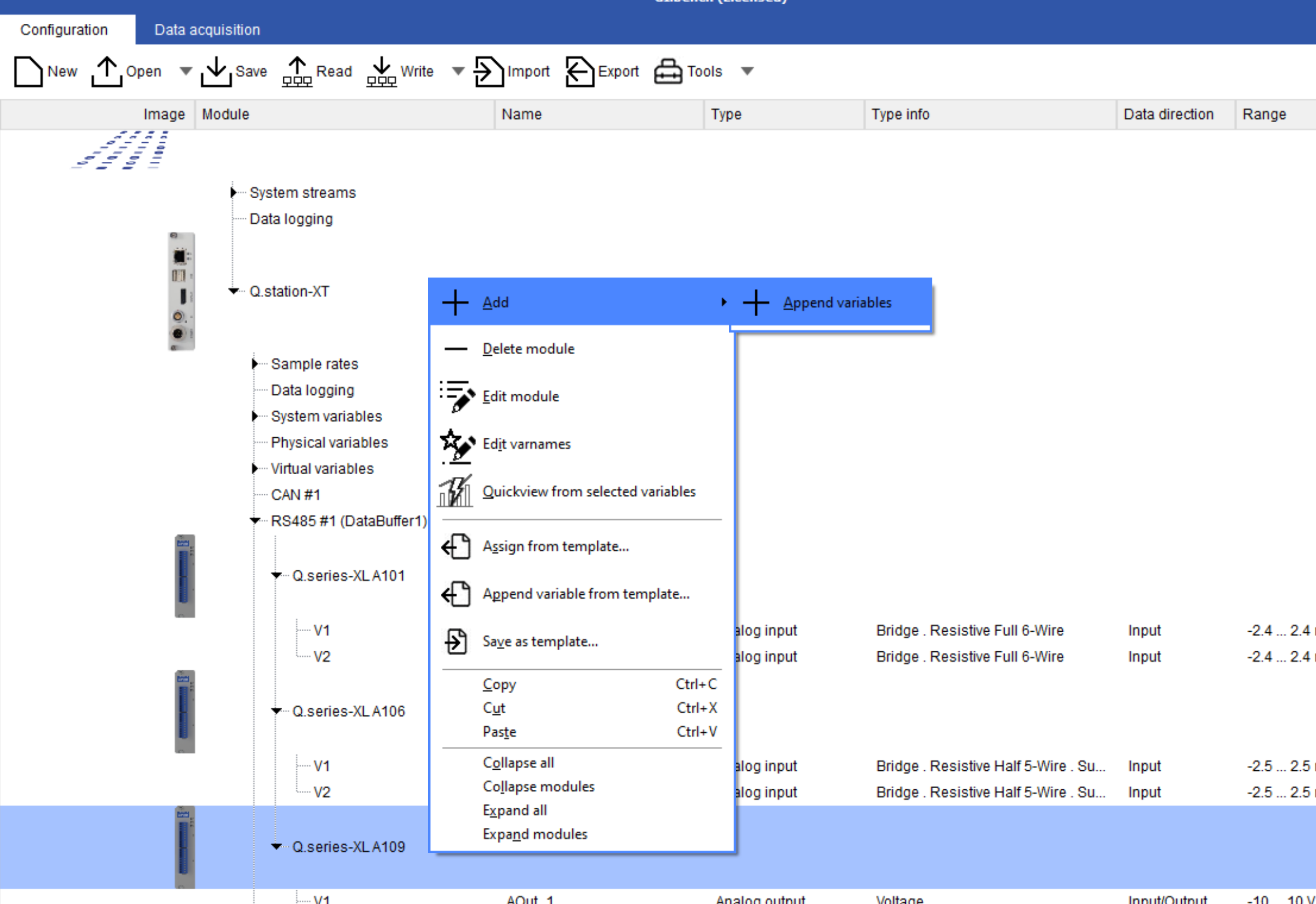
- Open configuration in GI.bench project window
- Right-click module and select Add > Append Variable
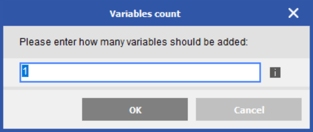
- Enter a value of 1 and click OK
- Double-click new variable to open variable settings. Keep the Type as a Setpoint
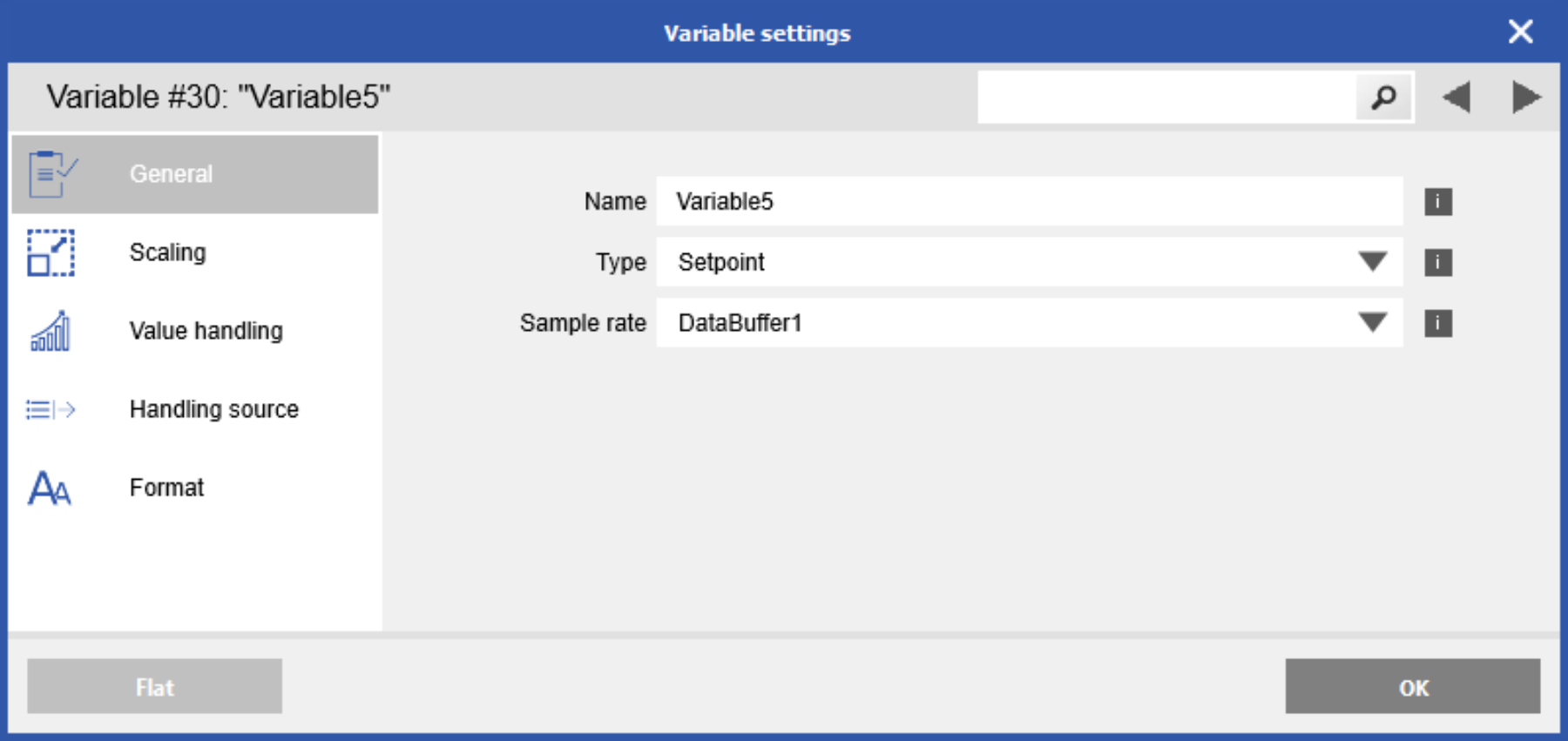
- Navigate to the Handling source section.
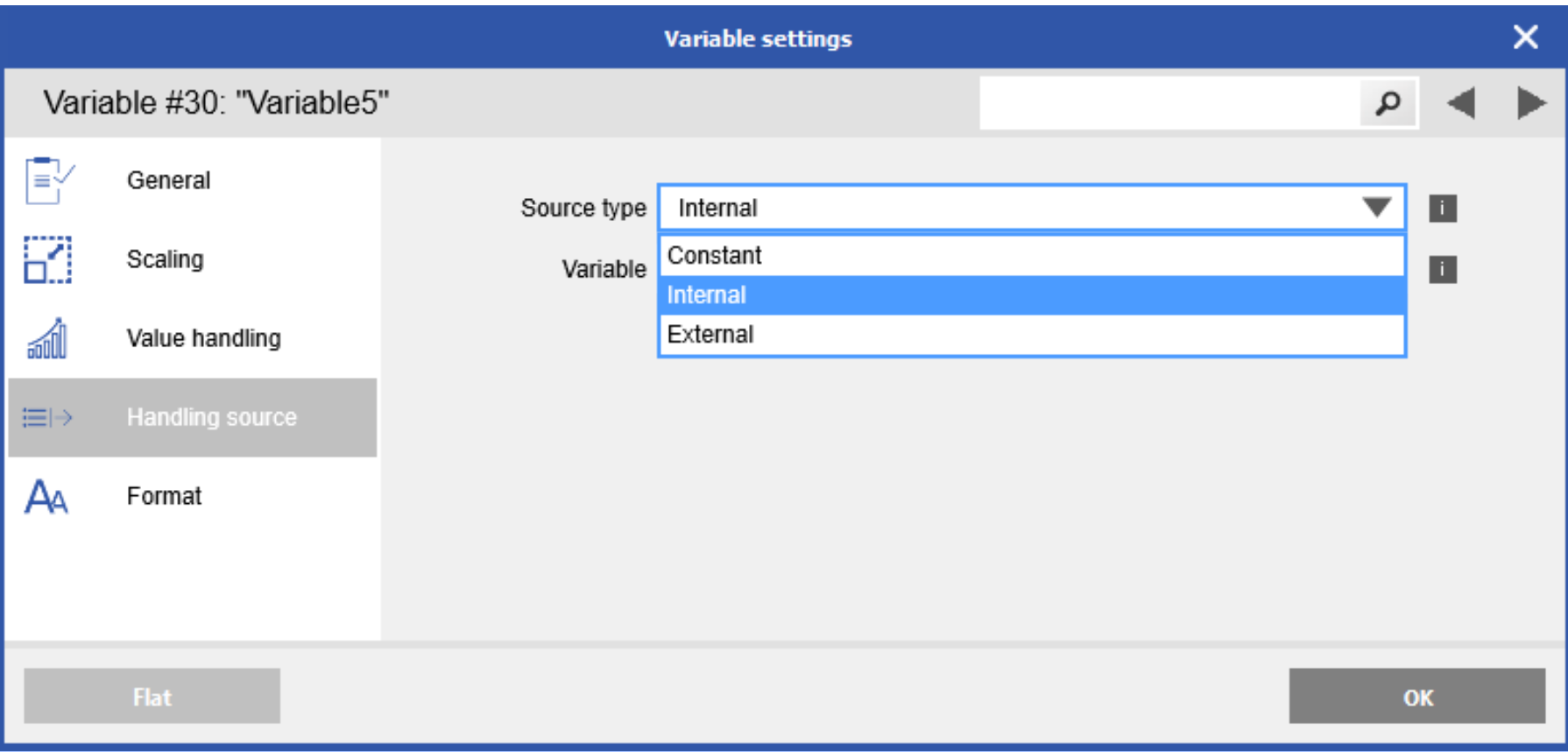
A Setpoint's source variable can be Internal, External, or Constant. Internal
meaning another variable within the same measurement module. External means a variable on a module connected to the same UART. Constant means a known fixed value can be applied. - Select External for this example to communicate with a different measurement module on the same system.
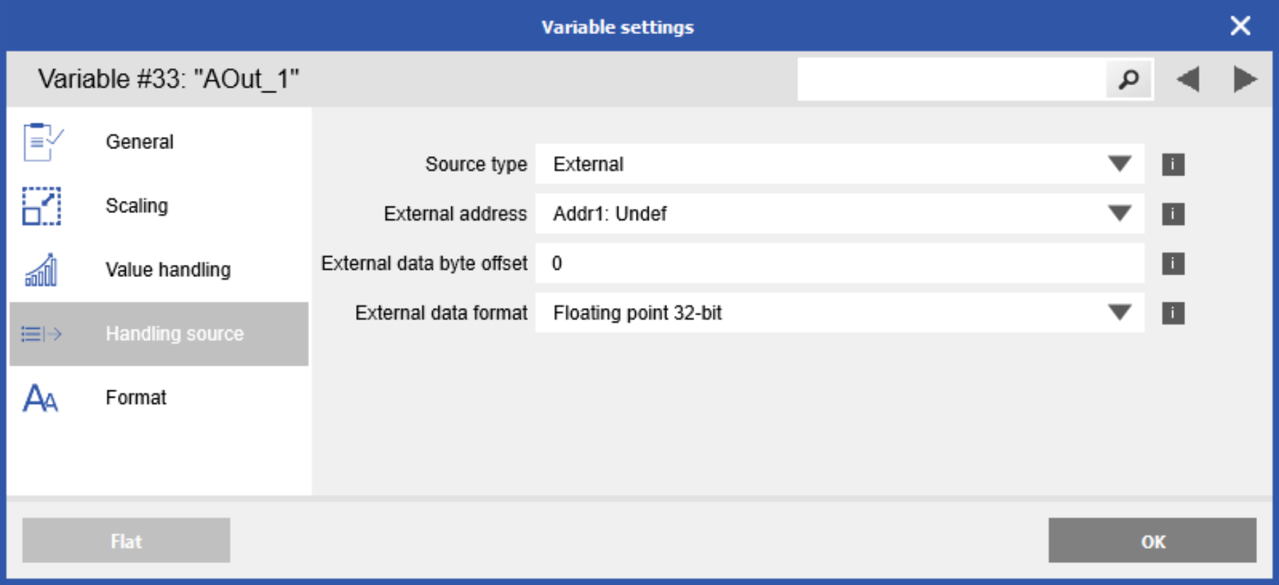
- Notice that the Address, Byte offset, and Data Type drop-down options appear when External is selected.

- External Address: refers to the address of the external module. For example, our system consists of a Q.station XT, A101, A106, and A109.
- Address 1: Q.bloxx XL A101
- Address 2: Q.bloxx XL A106
- Address 3: Q.bloxx A109
Select Addr1 to select the source signal from the A101
- External Address: refers to the address of the external module. For example, our system consists of a Q.station XT, A101, A106, and A109.
-
- External data byte offset: refers to the location of the desired variable within its respective module. For example, the A101 module has 2 channels configured, we would use the following Byte offset to obtain the desired variable:
Variable inside A101 Byte offset Variable 1 0 Variable 2 2 - External data format: default for most data measured by the Q.series modules are floating points (single).
- External data byte offset: refers to the location of the desired variable within its respective module. For example, the A101 module has 2 channels configured, we would use the following Byte offset to obtain the desired variable:
- Click OK to save variable changes, then write updates to the DAQ system
Please note that in future releases of GI.bench (scheduled for 03/2025), the term "Byte offset" will be updated to "Register Offset" to better reflect its function.
Procedure (test.commander/ICP-100)
- Open the desired module in ICP100.
- Add a virtual variable to the module, specifically a Setpoint.
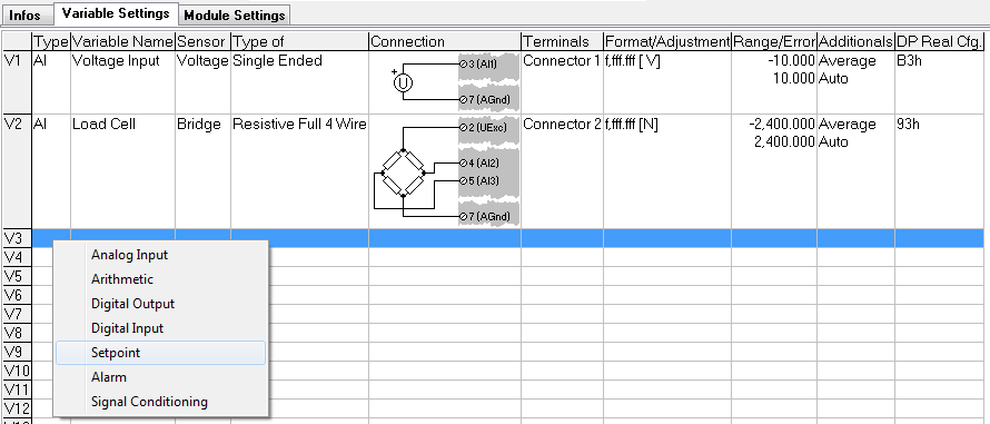
- Double-click the cell under the Additionals column. This will bring up the window below:
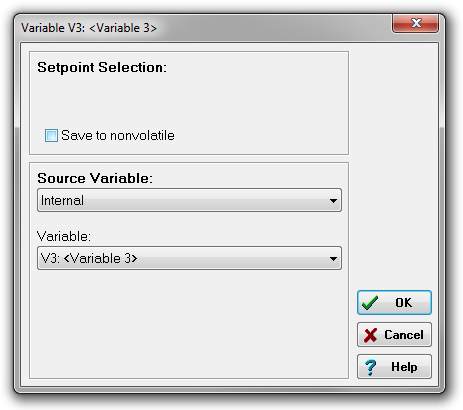
- A Setpoint's source variable can be Internal, External, or Constant. Internal
meaning another variable within the same measurement module. External means a variable on a module connected to the same UART. Constant means a known fixed value can be applied. - We will select External for this document to communicate with a measurement module on the same system.
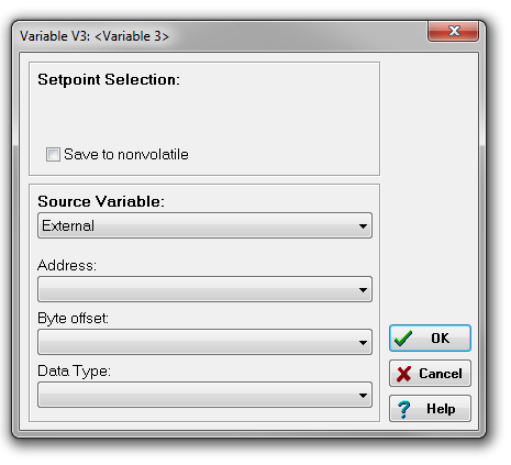
- Notice that the Address, Byte offset, and Data Type drop-down options appear when External is selected.
- Address: refers to the address of the External module. For example, our system consists of a Q.station, an A101, and an A104, where the A101 is address 1, and A104 is address 2. If we are configuring a Setpoint inside the A101 and want to use a variable inside the A104, we would select an Address of 2.
- Byte offset: refers to the location of the desired variable within its respective module. For example, the A104 module has 8 x TC channels configured, we would use the following Byte offset to obtain the desired variable:
Variable inside A104 Byte offset Variable 1 0 Variable 2 2 Variable 3 4 Variable 4 6 Variable 5 8 Variable 6 10 Variable 7 12 Variable 8 14
- Data Type: all data measured by the Q.series modules are floating points (single).
- Make sure to confirm the settings by clicking OK. Save the module and update the project to the controller.
For long time users: The data Byte Offsets have been switched to register offsets. This will require adjustments to older test.commander projects with this feature. New module firmware will handle the offsets as register offsets.