How to time synchronize multiple controllers

How to synchronize the clock of two or more controllers to ensure identical time-stamping of all measurement data

The synchronization of multiple controllers is done with Q.sync over RS482. This feature allows all I/O modules (local or distributed) to operate synchronously with a maximum jitter of ±0.5 µs across all channels. This article will explain how to set up the controller synchronization with either GI.bench or test.commander software.

The channels connected to a specific controller obtain their timestamp from that controller. Therefore, all controllers within a single system need to share the same time stamp. A master controller is designated and all subsequent slave controllers receive their time stamps from this master. This is done by connecting the Sync lines one to one from one controller to another:

CONTROLLER 1 CONTROLLER 2
SyA SyA
SyB SyB

Hardware setup

  1. Designate a controller as the master clock.
  2. Connect the Sync lines from the master to all subsequent controllers in a daisy chain connection. The maximum length for the sync lines is 400 m (approx. 1300 feet).

Software configuration

GI.bench

  1. Connect the master controller via Ethernet to the PC running the GI.bench software.
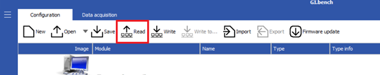
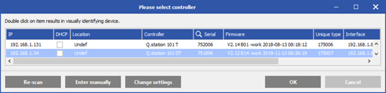
  2. In GI.bench, click Read to scan the network for the connected controller.
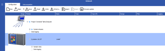
  3. Highlight the master controller, and click OK to load the configuration to the project window.
  4. After the configuration loads, double-click on the controller to open its settings:
  5. Navigate to the Synchronization section and make sure the Hardware sync. is set to None for the master controller (default setting):
  6. Click OK to confirm the setting changes and update the configuration to the controller by clicking on Write on the toolbar
  7. Connect all subsequent controllers one at a time to the PC running GI.bench.
  8. In GI.bench, repeat previous steps to open the controller’s settings and navigate to the Synchronization section.
  9. Make sure the Hardware sync. for all slave controllers is set to Q.sync over RS485:
  10. Click OK, then Write to update the configuration to the controller.

test.commander

  1. Connect the master controller to the PC running the test.commander software.
  2. In test. commander, open a project and right-click anywhere in the project window, and select Add Online Controllers.
  3. After it scans the network for controllers, highlight the controller and click OK.
  4. Double-click on the controller to open its settings:
  5. Navigate to Settings > Synchronization and make sure the Input synchronization protocol is set to none for the master controller (default setting):
  6. Click OK to confirm the setting changes and update the configuration to the controller by clicking on File > Write Project Update.
  7. Connect all subsequent controllers one at a time to the PC running test. commander.
  8. In test.commander, repeat previous steps to open the controller’s settings and navigate to the Synchronization section.
  9. Make sure the Input synchronization protocol for all slave controllers is set to Q.sync over RS485:
  10. Confirm setting changes and write the updated configuration to the controller.

Sync controller with an external time source (optional)

Optionally the master controller can synchronize its clock to an external time source. For more information, please refer to the article on how to synchronize a controller with an external time source.