Introduction
The Q.station X controller features four UART interfaces for RS-485 communication with Q.bloxx XL modules. The RS-485 bus can connect via a backplane (integrated into the module socket) or by wiring for remote installations. In both cases, all modules are automatically time-synchronized with ±0.5 µs jitter..
Each UART supports up to 16 modules, allowing a maximum of 64 modules per controller. The number of modules and data throughput depend on the baud rate, which is influenced by the total RS-485 bus length. See the section Baud rate versus bus length for details.

RS-485 bus wiring with extension sockets
To connect the controller and measurement modules via a wired bus, extension sockets are required. These adapters convert the PCB backplane connector into screw terminal connectors for easy wiring. Extension sockets provide connections for both RS-485 bus communication and module power supply.
There are two versions of the extension socket:
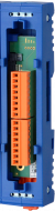
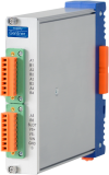
- LEFT: connects to the module’s left side, converting screw terminals back to the backplane connector. Q.bloxx-X base left for UART and Supply, Article No. 544021 (datasheet)
- RIGHT: connects to the module’s right side, converting the backplane connector to screw terminals. Q.bloxx-X base right for UART and Supply, Article No. 544122 (datasheet)
Q.bloxx XL extension sockets:
-
Q.bloxx-X base left for UART and Supply, Article No. 544021 (datasheet)
-
Q.bloxx-X UART/Power left, Article No. 561323 (datasheet)
Q.brixx XL extension modules:
-
Q.brixx-X UART/Power right, Article No. 611622
-
Q.brixx-X UART/Power left, Article No. 646327
Extension socket pin assignment and wiring
Pins 1 and 2 on connector X10 (UART 1) must be wired. Wiring the other UARTs is optional based on system configuration.
A 10–30 VDC power supply must be connected to pins 6 and 7 on connector X11 of the LEFT extension socket. This power can come from the controller (via the RIGHT extension socket) or a separate supply.
The pin assignment is identical for both LEFT and RIGHT extension sockets.

| Connector X10 | |||
| 1 | RS485 1 A | UART 1, signal A | Mandatory |
| 2 | RS485 1 B | UART 1, signal B | Mandatory |
| 3 | RS485 2 A | UART 2, signal A | Optional |
| 4 | RS485 2 B | UART 2, signal B | Optional |
| 5 | RS485 3 A | UART 3, signal A | Optional |
| 6 | RS485 3 B | UART 3, signal B | Optional |
| 7 | RS485 4 A | UART 4, signal A | Optional |
| 8 | RS485 4 B | UART 4, signal B | Optional |
| Connector X11 | |||
| 1 | RS485 ACYCL A | Acyclic data exchange | Not used |
| 2 | RS485 ACYCL B | Acyclic data exchange | Not used |
| 3 | DIG slot | - | Not used |
| 4 | VS+ | Add. sensor excitation supply | Optional |
| 5 | VS- | Add. sensor excitation ground | Optional |
| 6 | VIN | Module power supply 10 - 30 VDC | Mandatory |
| 7 | GND | Module power supply ground | Mandatory |
| 8 | CGND | Chassis ground | Optional |

Baud rate versus bus length
Depending on bus length, the data transmission speed (baud rate) may need to be reduced. The factory default is 24 Mbps. See the table below for recommended baud rates.
The controller’s baud rate is configured in GI.bench (Controller → RS485 adapter → General → Baudrate). GI.bench verifies whether the configured modules, variables, and sample rate fit within the selected baud rate. If an error occurs, reduce the number of modules/variables on the UART or lower the sample rate.
The total bus length includes all cables between modules and the cable to the centralized controller. Regardless of cable length or baud rate, each UART supports up to 16 modules. For baud rates of 1.5 Mbps or lower, maintain at least 1 meter of cable between adjacent devices.
A baud rate of 48 Mpbs can only be used with a backplane bus, not with a wired bus.
| Baud rate | Maximum bus length |
|---|---|
| 187.5 kbps | 1000 m |
| 500 kbps | 400 m |
| 1.5 Mbps | 200 m |
| 3 Mbps | 100 m |
| 6 Mbps | 20 m |
| 12 Mbps | 10 m |
| 24 Mbps | 10 m |
| 48 Mbps | backplane only |
Bus Termination:
The modules of the Q.series-X have an internal termination resistor of 50 ohms.
This is optimised for relatively short cables and a high baud rate (up to 48 Mbit).
However, it is not optimal for long bus cables.
In such cases, it is better to follow the Profibus standard and use resistors of approximately between 50 and 120 ohms.
Ultimately, however, it is often a matter of trial and error to determine which resistor works best for a given application (amount of modules, cable type, cable length).
If you use an external termination resistor, please do not set DIP switches 9 and 10 (set them to OFF). Put the external resistor between A and B.
Cable requirements
The recommended baud rates apply only when using PROFIBUS cables compliant with the IEC 61158 standard. Using other cables may invalidate these recommendations and affect long-term reliability.
To reduce electrical interference, use cables manufactured to IEC 61158 (Type 3 or PROFIBUS cable). These are 2-wire shielded twisted pair cables, typically with Aluminum Polyester Tape shielding and either tinned copper wire braid (TCWB) or steel wire armor (SWA) to protect against crosstalk and electromagnetic interference.
Note that some cables designed for special environmental conditions may not meet the specified bus length or reliability requirements. Refer to the cable manufacturer’s datasheets for details.
Gantner Instruments recommends the UNITRONIC BUS PB cables from LAPP.