This procedure has been tested with TwinCAT 2 and TwinCAT 3 (integrated into Microsoft Visual Studio): V3.1.4016.0 / V3.1.4018.4 / V3.1.4018.26 / >= V3.1.4020.0 (running on Windows 10).
Download
You can download TwinCAT directly from the Beckhoff website:
Setup
-
Install TwinCAT on a PC equipped with an EtherCAT-compatible network interface card (NIC).
-
Connect an Ethernet cable from the PC to the EtherCAT IN port of the Q.station controller or EtherCAT bus coupler. Ensure that the controller's Fieldbus Interface is configured for EtherCAT.
-
Copy the EtherCAT Slave Information (ESI) file from the Gantner Instruments software installation directory to the appropriate TwinCAT ESI directory.
-
GI.bench: C:\Users\Public\Documents\Gantner Instruments\GI.bench\additionals\EtherCAT\Gantner Instruments.xml
-
test.commander: C:\Users\Public\Documents\Gantner Instruments\test.commander\Additionals\EtherCAT\Gantner Instruments.xml
-
TwinCAT 2: C:\Program Files\TwinCAT\Io\EtherCAT
-
TwinCAT 3: C:\TwinCAT\3.1\Config\Io\EtherCAT
-
Network Adapter
TwinCAT does not support all PC Ethernet adapters for use as an EtherCAT master. Beckhoff officially supports only selected network adapters, primarily those based on Intel chipsets. Before installing TwinCAT, verify that the PC is equipped with a supported network adapter. A list of compatible EtherCAT master network adapters is available on the Beckhoff website: Support Network Controllers by Beckhoff
The Device-ID of a network adapter can be found in the properties of the device in “Details” → “Hardware Ids”:

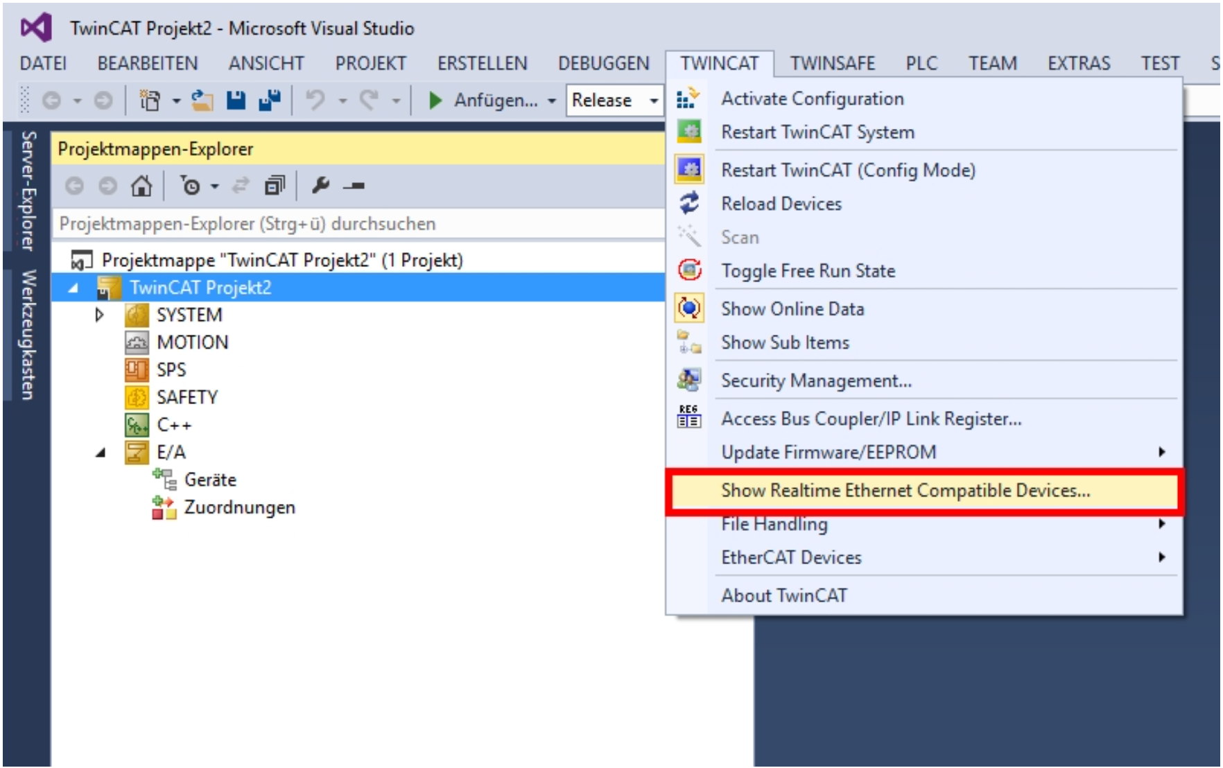
After creating a new TwinCAT project in Microsoft Visual Studio, verify that a TwinCAT-compatible real-time Ethernet adapter is available. To do this, select TwinCAT → Show Real Time Ethernet Compatible Devices... from the menu.
In the next window, at least one Ethernet adapter must be listed under Installed and Ready to Use Devices. If no adapter is shown, the network interface is not supported for use as a TwinCAT EtherCAT master.

Depending on the PC hardware, it may be necessary to adjust the following BIOS settings:
- Disable Hyper-Threading (particularly on Intel Core i7 processors).
- Enable Intel Virtualization Technology (VT-x), which is required when using the 64-bit version of TwinCAT 3.
Reading Data
Scan Bus
Open a new TwinCAT project and right-click on I/O Devices. Select the network device (checkbox on EtherCAT), allow Scan for boxes, and Activate Free Run.

At I/O Devices a new device is created and set to OPERATIONAL. You can already see channel data by selecting a device:

Run Mode
After configuring the EtherCAT master as described above, create an additional TwinCAT task (see screenshot) and enable Auto Start. This ensures that TwinCAT transitions from Free Run mode to Run mode.
To exchange data, create the required input variables (for example, xxxx and yyyy) by right-clicking Inputs. Configure each variable with the appropriate data type and map it to the corresponding controller variable using the Linked to... button.
To apply the configuration and start operation, click Activate Configuration in the toolbar. TwinCAT will then download the configuration and switch to Run mode.
Configuration
Q.series XE system (with bus coupler) using GI.bench
The GI.bench full software features the ability to communicate with the TwinCAT master over FoE for the configuration of the DAQ system.
This is only possible with a bus coupler (e.g. Q.bloxx XE BC, Q.bloxx EC BC)
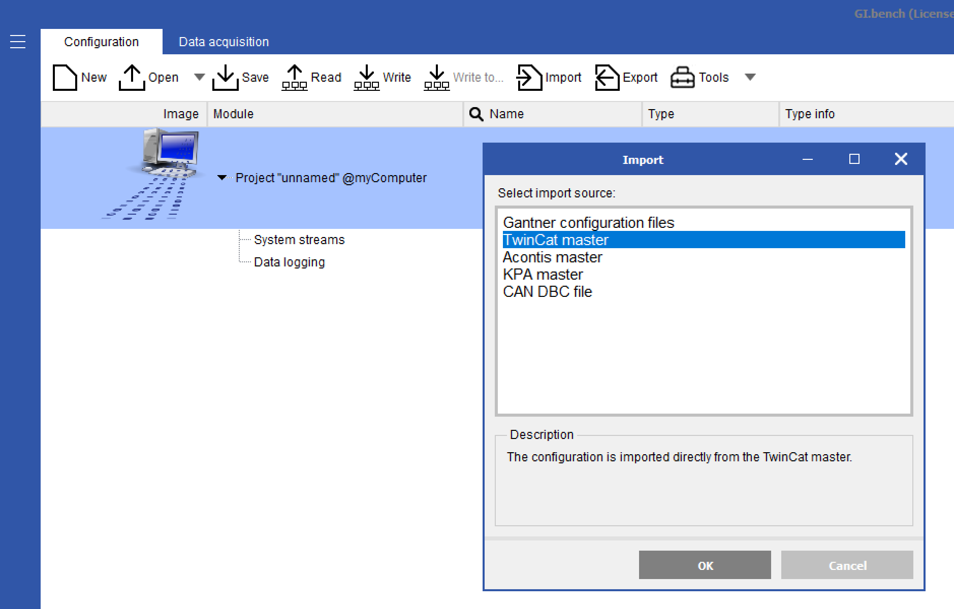
- With a fully licensed GI.bench click Import > TwinCAT master. If not running already, this should automatically start the TwinCAT service (GI.twincatfoe).
- Enter the NetID from the TwinCAT master. If connected directly to the system you can leave it blank for local service

- The configuration of the connected measurement modules will load into the GI.bench project window. The bus coupler will just appear as a virtual device

- Configure the modules and channels as needed
- To download the changes to the modules click Export > TwinCAT master. This exports the configuration directly to the TwinCAT master to be transferred to the modules
Q.series XE system (with bus coupler) using ICP 100
The bus coupler can be connected to the PC through its USB port for serial communication to configure the modules
- Connect a cable from the bus coupler's Micro USB port to the PC
- Take note of the COM port used on the PC for this connection
- Run ICP-100 software
- Go to Communication > Parameters. Change Interface Kind to RS232 Direct and select corresponding ComPort. Click OK.

- Go to File > Scan Bus to scan for connected hardware
- Select from the drop-down list the connected modules
- The module configuration will be loaded, and make required changes
- Go to File > Send to Module to download the configuration to the hardware
- Repeat steps 6 through 8 for any other connected module
Q.station 101 or Q.station X EC using GI.bench
Communication for configuration is done through the Ethernet port to the PC to the software
- Click Read and scan the network for the connected controller and click OK
- After configuration is loaded into the project window, make the required configuration changes
- Click Write to download the configuration to the hardware
- Rescan configuration in TwinCAT to show changes