Purpose:
This article describes how to use our DAQ configuration software (GI.bench/test.commander) to load different projects to a controller to quickly have different setups for the same hardware.
The hardware (including the controller and measurement modules) must match exactly what is used in the loaded project configuration, or else the controller will not accept it. The individual projects must initially be created and modified but can be saved and used for future tests.
Procedure (GI.bench)
- Install GI.bench, assemble hardware, and connect communication & power lines.
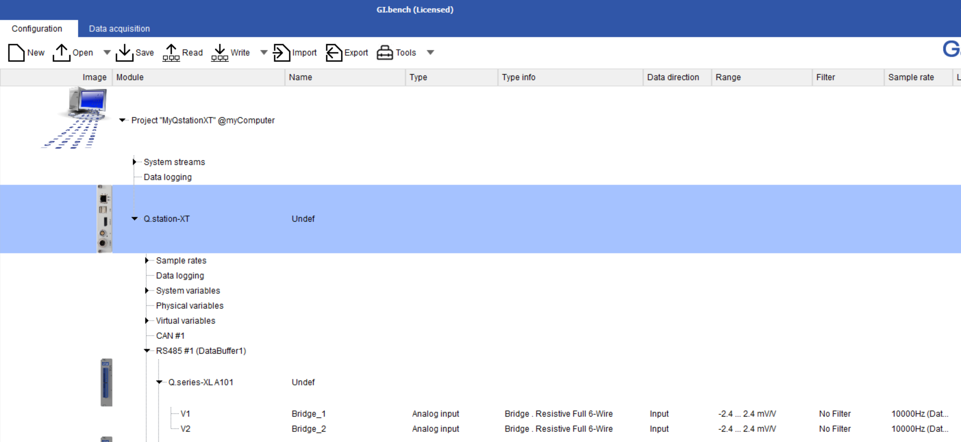
- Open GI.bench and click Read to load current configuration of DAQ system into project window
- Configure this project as needed. For this example we will configure the A101 module's channels to measure bridge inputs
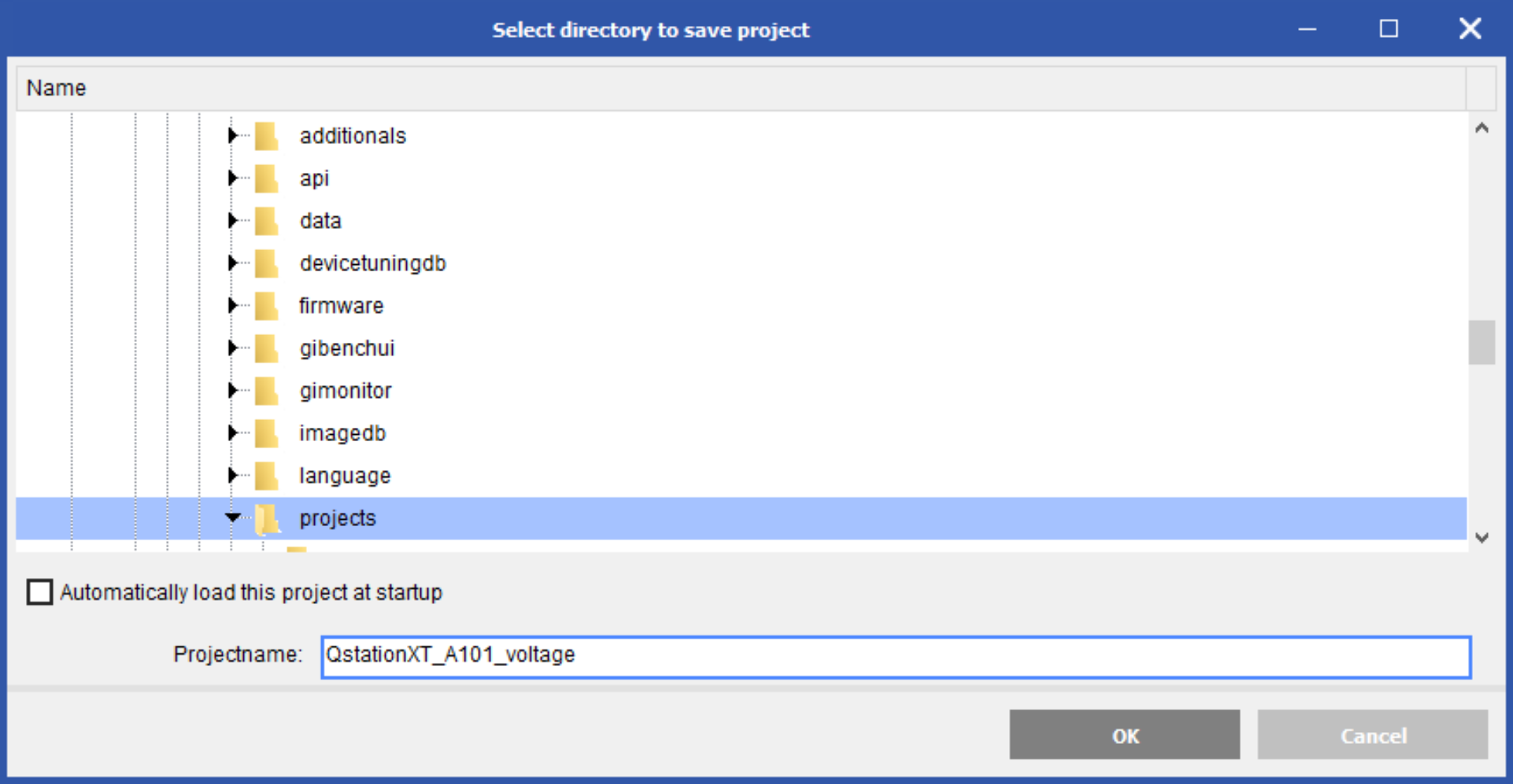
- Click Save (or Write which will prompt to save project and write updates to controller) and give the project a name

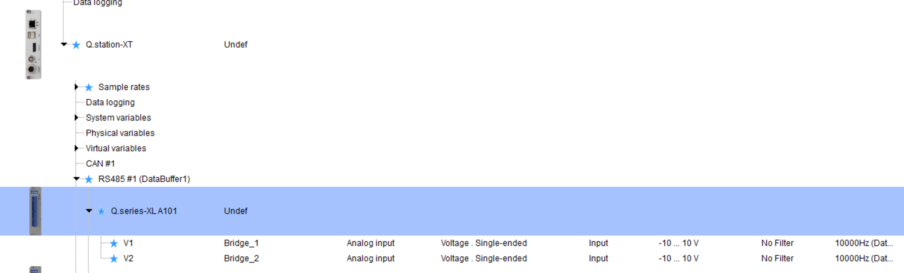
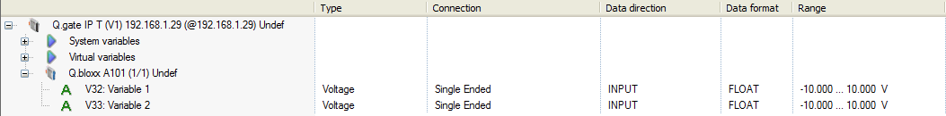
- Now configure 2nd setup. This example we will now configure the A101 inputs to measure voltages
- Click Save (or Write) to save this as a different project. Make sure to give it a different name from the 1st project
- Now when you want to switch back and forth between each setup, load the desired project by clicking Open under the Configuration tab
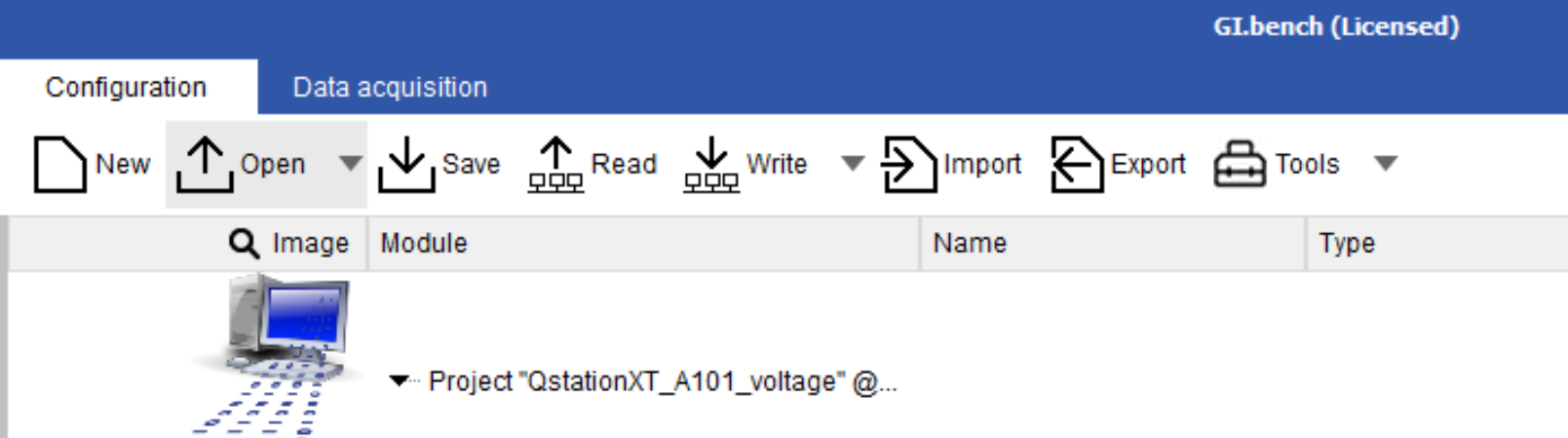
- Open the desired project, then click Write to load the configuration onto the DAQ system. Repeat as needed for when you need to switch to a different setup.
Procedure (test.commander):
- Install test.commander, assemble hardware, and connect communication & power lines.
- Open test.commander and create a new project (File > New Project). For this example, we will call the project “PROJECT-VOLTAGE.” This will create a blank project.
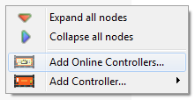
- Anywhere in the workspace area of test.commander, right-click on your mouse and select “Add Online Controllers.”
- Follow the on-screen instructions to add the current configuration inside the controller to this new project. When finished, the most recent configuration will be loaded under “PROJECTVOLTAGE.”
- Close the “PROJECT-VOLTAGE” window.
- Create a new project again (File > New Project). For this example, we will call the project
“PROJECT-TC”. This will again create a blank project. - Again, anywhere in the workspace area of test.commander, right-click on your mouse and select “Add Online Controllers.”
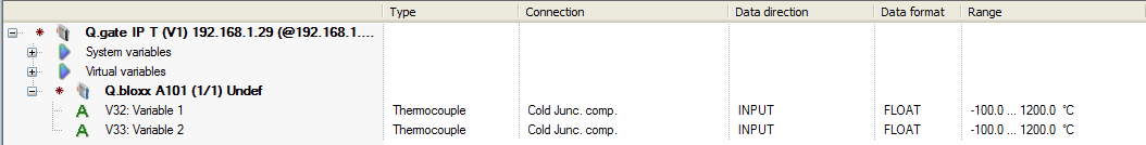
- Follow the on-screen instructions to add the current configuration inside the controller. When the project finishes being downloaded from the controller, notice that the configuration is the same as the previous. We can now modify this project, “PROJECT-TC,” with different settings. For example, let’s configure the channels as thermocouples:
- At this moment, there are 2 options we can perform. (1) Upload the “PROJECT-TC” to the
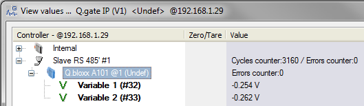
controller or (2) save the “PROJECT-TC” to be used for a future test. For example purposes, we will upload the “PROJECT-TC” to the controller (File > Write Project (Update)). - After the project has been updated, view online values to verify that the A101 is indeed
configured as TC channels (File > Read Online Values from Controller).
(Image above shows open channels, hence full-scale value)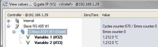
- At this moment, we want to switch to another project, “PROJECT-VOLTAGE.” Close the
“PROJECT-TC” window. Select File > Open Project. Find the .EPJ file for the project you wish to use. The default directory where all Gantner Instruments projects are saved in is:
C:\ProgramData\Gantner Instruments\test.commander\Projects - Select the .EPJ and the new project window will appear. Make sure the red star is present before updating.
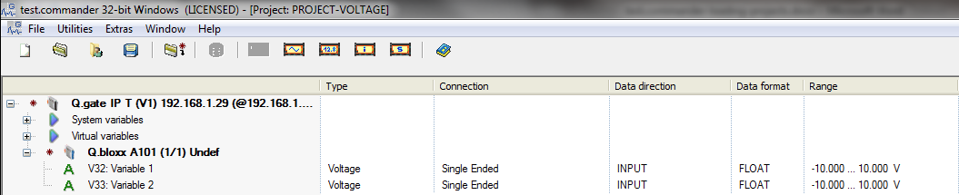
- Upload this project to the controller (File > Write Project (Update)). After the project finishes updating, view the online values to verify that the A101 is configured as voltage channels.
- This process can be repeated for multiple projects and various configurations.
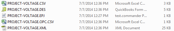
- If creating a backup of the project configuration is desired, this is possible by selecting File > Export Project. This will create a ZIP file that contains all the configurations for that specific project.
- A complete project contains the following items:
- A folder with the same name as the project name containing the module configuration settings for every module in the project.
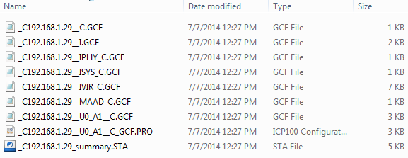
- The following project settings files.
- A folder with the same name as the project name containing the module configuration settings for every module in the project.
- These configuration files should not be edited using software other than
test.commander/ICP100. The contents of the files can be viewed using Notepad if necessary. If these files are modified incorrectly, it can result in errors that can only be resolved at the factory.
Example: A101 configuration file: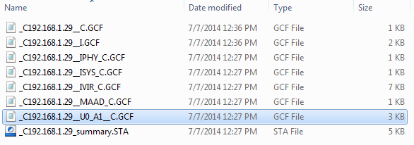
- If the hardware configuration ever changes, the settings inside the controller must be reset before uploading new configurations. The projects must also be reconfigured to reflect the hardware changes.