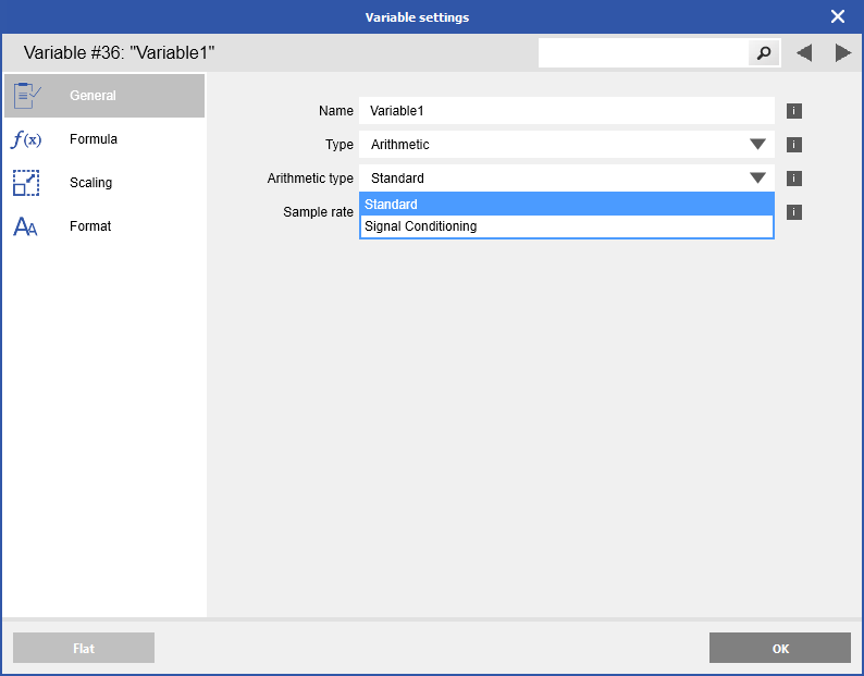
For Q.series DAQ modules, the same functions (e.g., selRMS, max, min) can be configured either as standard arithmetic variables or as signal-conditioning arithmetic variables.
The difference lies in where the calculation is executed:
- Standard arithmetic variables are processed in the DSP, using values read from the FPGA.
-
Signal-conditioning arithmetic variables are calculated directly in the FPGA, working with raw or internally processed signals.
Standard arithmetic functions
These functions are computed in the DSP and are affected by CPU load, which can impact their speed and performance.
-
-
- +
-
*
-
/
-
min()
-
max()
-
selRMS(Vx; Ts) ... Ts = integration time (period of the processed signal)
-
integ()
-
spec1()
-
spec2()
-
spec3()
-
spec4()
Signal conditioning arithmetic functions
These functions operate inside the FPGA, leveraging direct processing at the module's sample rate for faster and more precise calculations.
-
min() … min value of an analog or remote input
-
max() … max value of an analog or remote input
-
selunb() … analog input unbalanced value (Raw)
-
selgro() … gross value Gro = Raw - null
-
selnet() … netto value Netto = Gro - tare
-
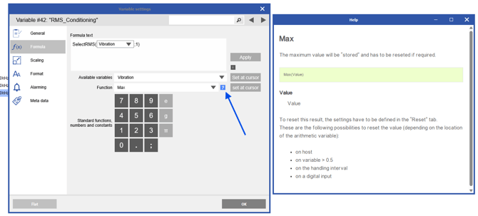
selRMS(Vx; Ts) … Ts LP rise time (should be several periods of the processed signal)
-
selmul() … multiplies 2 following analog input channels (Ain0*Ain1, Ain1*Ain2, …)
-
spec1()
-
spec2()
-
spec3()
-
spec4()
Processing Differences: DSP vs. FPGA
The performance and precision of these calculations depend on whether they are executed in the DSP or the FPGA:
-
DSP-based calculations: Execution speed depends on CPU load. When CPU load is high, calculation performance might degrade.
-
FPGA-based calculations: These run in direct relation to the module's configured sample rate, providing higher precision and faster results without CPU load constraints.
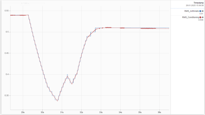
Example: RMS Calculation Comparison
Below is an example demonstrating the difference between DSP-based arithmetic and FPGA-based signal conditioning using RMS calculations. The YT-chart screenshot highlights the contrast:
-
Blue Line: RMS calculation via DSP-based arithmetic
-
Red Line: RMS calculation via FPGA-based signal conditioning
The signal conditioning RMS calculation shows significantly more data points and provides a more accurate result compared to the DProcessing Differences: DSP vs. FPGA
Supported Arithmetic and Signal Conditioning Functions
Not all functions are supported on every Q.series X module. Function availability depends on the module’s design and capabilities, including:
-
Maximum number of channels supported by the module
-
Transfer-rate limitations (e.g., UART or other interfaces)
-
Available FPGA processing resources for signal-conditioning operations