Introduction
Potentiometers, commonly referred to as "pots" among engineers, function as variable resistors primarily used for measuring linear or rotary (angular) displacement. Operating as voltage dividers, they produce a continuously adjustable voltage output signal proportional to the physical position of the wiper on the resistive element. As passive sensors, potentiometers do not need a power supply to operate.
A potentiometer can be read using one of the following Q.series modules:
- Q.series A101 for measurements up to 100 kS/s
- Q.series A107 for measurements up to 20 kS/s
- Q.series A121 for measurements requiring high-voltage galvanic isolation
Connecting a potentiometer
The Q.series modules are compatible with potentiometers having an overall resistance value between 1 and 10 kΩ (kilohms). This resistance value represents the entire resistance element, spanning from one terminal to the other.
All modules support the standard three-wire configuration. The specific sensor wiring details depend on the module and socket type. For precise information, please consult the datasheet, user manual, or refer to the sensor connection details in GI.bench.
Scaling to an engineering unit
A potentiometric measurement is a ratiometer measurement; the measured value is directly proportional to the excitation voltage. Given its relative nature, the unscaled potentiometer measurement using an A107 module has a default range from 0 to 1 V/V.
2-point measurement
To scale a potentiometer to engineering units, it is recommended to perform a 2-point scaling using live measurement values. In this process, the actual measurement value is compared to a calibrated reference value, allowing the calculation of corrective gain and offset. This approach provides the advantage of compensating for inaccuracies throughout the entire measurement chain, a practice commonly referred to as end-to-end calibration.
The 2-point scaling method assumes a linear behavior of the sensor throughout its entire range. In the case of a non-linear sensor, it is necessary to establish a multi-point scaling using the sensor database functionality available in GI.bench.
2-point calculator
If end-to-end calibration is not feasible, for instance, due to the sensor being fixed in position or the lack of a reference measurement, an alternative method involves using a valid calibration certificate for the sensor. Typically, this certificate details the voltage output of the sensor, the corresponding engineering unit value, and the specific excitation voltage to which these calibration values apply.
In this example, we will examine a linear potentiometer using the information provided on its calibration sheet.
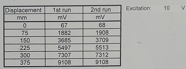
In GI.bench, 2-point scaling is done by entering both the physical unscaled value (V/V) and its corresponding engineering unit value (mm). The physical unscaled value is determined by dividing the sensor's voltage output by the excitation voltage, as specified on the calibration sheet.
In the below GI.bench example, the sensor's minimum and maximum positions have been used for scaling. In this scenario, the physical unscaled value for a 0 mm displacement is calculated as 0.068 V / 10 V = 0.0068 V/V, while for a 375 mm displacement, it is calculated as 9.108 V / 10 V = 0.9108 V/V.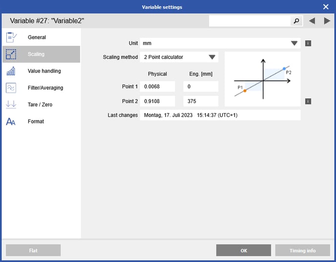
Non-linear sensor scaling
The majority of potentiometers in use are of the linear taper type, wherein the resistance between the contact (wiper) and one end terminal is directly proportional to the distance between them. Occasionally, logarithmic taper potentiometers are used. A logarithmic taper potentiometer features a built-in bias in its resistive element. Essentially, this implies that the center position of the potentiometer is not necessarily halfway between the two ends of its total value.
To scale a non-linear potentiometer, use the sensor database functionality in GI.bench for linearizing the sensor reading. Linearization facilitates the transition from physical to intermediate unit conversion, while the scaling feature handles the conversion from intermediate to engineering units.
- In the sensor database, create a new sensor by duplicating the existing potentiometer sensor.
- Set the intermediate unit as the desired default unit for the potentiometer (which can still be modified using the scaling functionality in GI.bench).
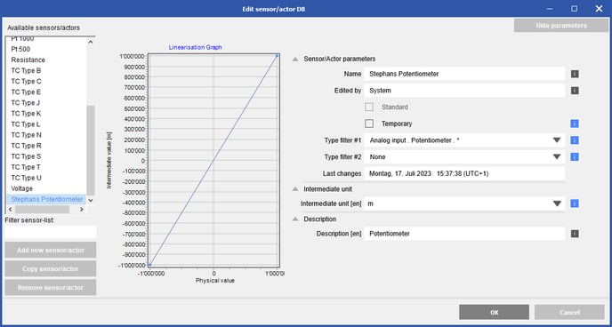
- Next, enter the linearization points into the sensor table. Similar to linear scaling, calculate the physical unscaled value by dividing the sensor's voltage output by the specified excitation voltage, as indicated on the calibration sheet. The intermediate values correspond to the preferred default engineering unit when this sensor is selected in a GI.bench project.
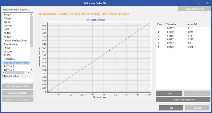
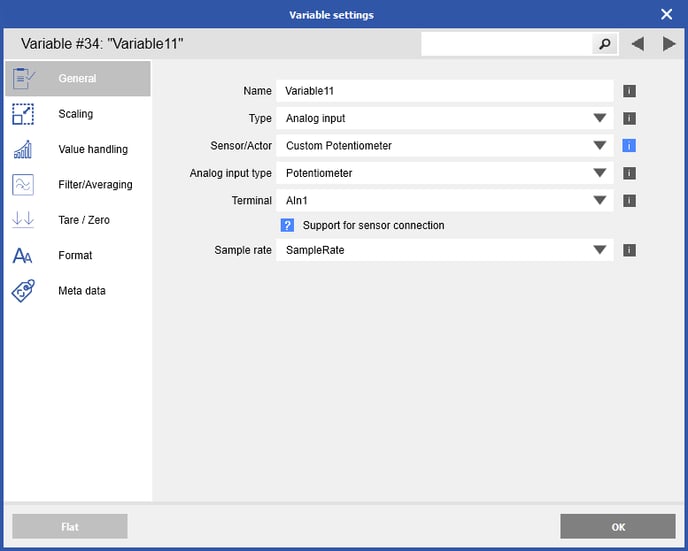
- Now, assign this newly created sensor to an input variable of the A107 module, and the linearization will be automatically applied.
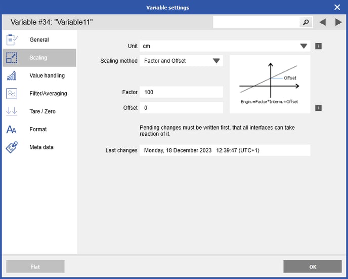
- If desired, the default engineering unit can be converted to another unit using the gain and offset, such as from meters (m) to centimeters (cm).