How does a quadrature encoder work?
Q.series modules for encoder measurement
Angle measurement
Counting number of revolutions
Angular velocity measurement
RPM measurement
Phase A/B pulse measurement
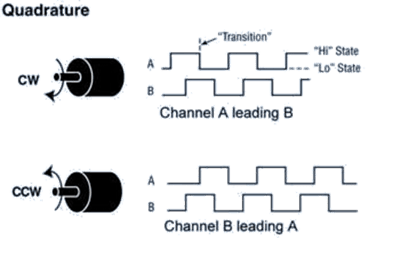
How does a quadrature encoder work?
A quadrature encoder is an incremental sensor that produces square wave output signals. It has two output channels known as Phase A (or Channel A) and Phase B (or Channel B). These signals are phase-shifted by 90°, determining the direction of the encoder's movement.
In addition to direction, position can also be tracked using a quadrature encoder by generating an additional index signal (often designated as Z, Index, or Marker channel). This index signal, generated once per complete revolution of the quadrature encoder, is frequently used to pinpoint a specific position during a 360° revolution.
A 2-wire quadrature connection allows Channel A (Phase A) and Channel B (Phase B) to be connected to the module, while a 4-wire quadrature connection also includes Channel Z (Index) and the option to connect an index enable signal (IndexEn).
The Index Enable acts as a gated switch that allows the system to capture the exact, single Z pulse per revolution, which is essential for precise rotational alignment. For general data acquisition applications, this channel is often not required.
Q.series modules for quadrature encoder measurement
Within the Q.series Classic and Q.series X data acquisition modules, the A109, D101, or D107 can be used for quadrature encoder measurements.
The A109 and D101 support single-ended encoder connections, while the D107 supports both single-ended and differential connections. Differential connections provide better signal integrity and are preferred when using long sensor cables.
|
A109 |
D101 |
D107 |
|
|
Counter, quadrature, 2-wire |
✅ (2 IN) |
✅ (4 IN) |
✅ (4 IN) |
|
Counter, quadrature, 3-wire |
❌ |
❌ |
✅ (2 IN) |
|
Counter, quadrature, 4-wire |
✅ (1 IN) |
✅ (2 IN) |
❌ |
|
Frequency, quadrature, 2-wire |
✅ (2 IN) |
✅ (4 IN) |
✅ (4 IN) |
|
State |
✅ (4 IN) |
✅ (8 IN) |
✅ (8 IN) |
Angle measurement
To measure angle, create a variable and set the digital input type to Counter and Quadrature. Then select the appropriate wiring configuration and the digital inputs to which the encoder is physically connected.

To scale the counter value to an angle in degrees, apply the following scaling factor:
φ [deg] = 360 / pulses per revolution
Example: for an encoder with 1024 ppr, the scaling factor is: 360 / 1024 = 0.3515625.

Alternatively, use the 2-point calculator. For example, assign 0 counts = 0° and set the ppr
(e.g., 1024) to correspond to 360°.

When Channel Z is connected, the index pulse resets the counter and therefore the angle reading to zero.
Counting number of revolutions
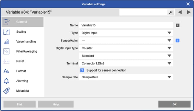
The number of revolutions is measured by counting complete 360° turns using the encoder Z (index) pulse. To measure the total number of revolutions, create a variable and set the digital input type to Counter and Standard. Then select the digital input to which the encoder Channel Z is physically connected ( typically DIin3 on Connector 1 or Connector 2).
Angular velocity measurement
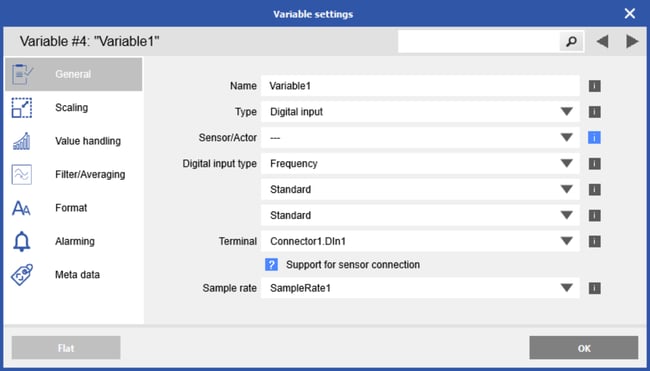
To measure angular velocity, create a variable and set the digital input type to Frequency and Quadrature. Then select the appropriate wiring configuration and the digital inputs to which the encoder is physically connected.

To scale the frequency value to an angular velocity in deg/s, apply the following scaling factor:
ω [deg/s] = 360 × frequency

RPM measurement
To measure RPM, measure the frequency of Channel A or Channel B. If the direction of rotation is not required, there is no need to configure the channel for counter or quadrature mode. Connect either Channel A or B of the encoder to a digital input and configure it for standard frequency measurement.
Once the frequency has been measured, it can be converted to RPM.
For example, with an encoder rated for a maximum speed of 8000 RPM and 360 pulses per revolution (ppr), the maximum frequency is:
fmax = 8000 rev/min x 360 pulses/rev / 60 s = 48000 pulses/sec = 48 kHz
Use the 2-point calculator and assign 0 Hz = 0 RPM and 48 kHz = 8000 RPM.

Enter an appropriate time base.
For high-frequency signals, a short time base is sufficient to count enough signal edges (transitions). For low-frequency signals, a longer time base is required to capture enough transitions and ensure accurate measurement.

Phase A/B pulse measurement
To measure the raw pulses of Channel A and/or Channel B, create a variable, set the digital input type to State, and select the digital input to which the encoder channel is physically connected.
