About the Q.station X EC
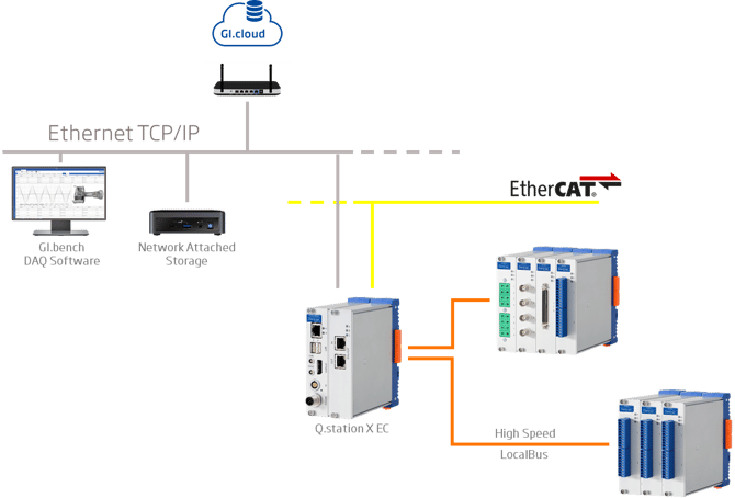
When combined with the Q.station X (B/T) EC, Gantner's Q.series X I/O modules provide accurate synchronization of measurement data and redundant high-speed data logging. The Q.station X EC serves as an intelligent protocol converter, enabling parallel communication through EtherCAT. As a single slave node in the EtherCAT network, the Q.station X EC supports up to 1024 bytes input and 1024 bytes output per communication cycle. This parallel communication feature ensures smooth data transmission to both an automation or supervisory control system via EtherCAT and to Ethernet, for example, to Gantner's PC-based data acquisition software, GI.bench.
Q.station X EC configuration and network setup explained
Step 1: Configuring the Q.station X EC and Q.series XL I/O modules
The Q.station X EC comes with a default configuration. The initial step involves connecting the Q.series XL modules following the instructions provided in the Q.series XL User Manual.
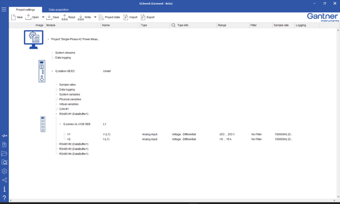
After successfully connecting the I/O modules, proceed to configure the measurement inputs using GI.bench, Gantner Instruments' PC-based Data Acquisition Software. Refer to the GI.bench How-To Guide for instructions on configuring a Q.station X-based system, or explore the GI.bench section in the knowledge base for tips and tricks.
Step 2: Enable the Q.station X EC EtherCAT slave interface
Activate the EtherCAT slave interface on the Q.station X EC controller by following the steps outlined below.
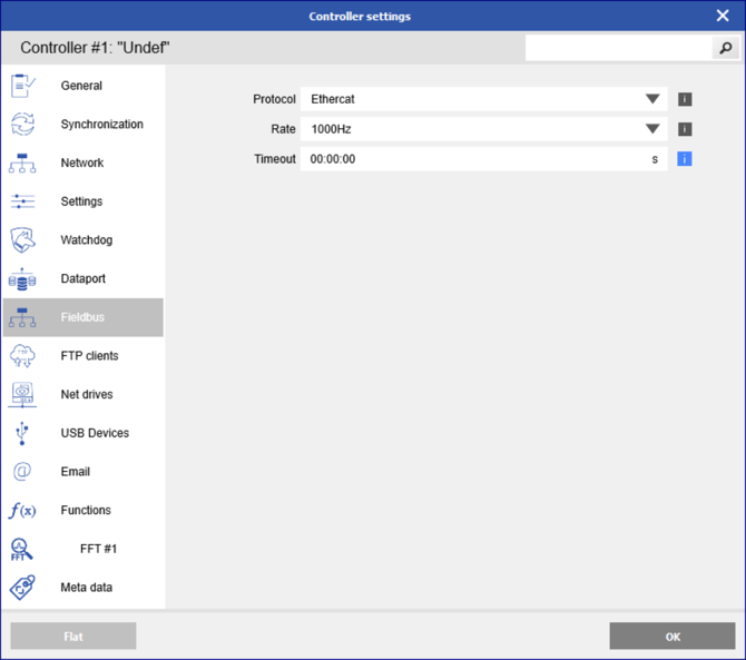
- In the controller properties, navigate to the fieldbus settings and choose EtherCAT. Specify the desired cycle frequency (Rate) to control the amount of data transferred, preventing overload on the EtherCAT bus. Optionally, set a timeout value to indicate communication errors in case of timeouts.
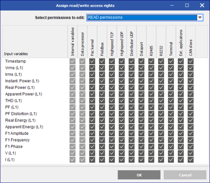
- Right-click on the controller, go to Edit -> Edit data access rights, and select which variables can read (from) and/or write (to) the EtherCAT bus in the Fieldbus column. By default, all available variables are enabled for read and write.
Step 3: Configuring the EtherCAT network
In configuring the Q.station X EC slave device within the EtherCAT master, two essential description files need to be taken into account: the EtherCAT Slave Information (ESI) file and the EtherCAT Network Information (ENI) file. The ESI file, specific to each device, provides details on the process data objects associated with that particular device. On the other hand, the ENI file outlines the network topology, initialization commands for each device, and cyclically transmitted commands. The EtherCAT master uses the information contained in the ENI file to initiate and configure the EtherCAT network.
In most cases, the EtherCAT master comes with a configuration tool to generate an ENI file using the provided ESI file(s) supplied by Gantner Instruments. Alternatively, the Beckhoff EtherCAT Configuration Tool can be used for this purpose.
Depending on the EtherCAT master's ability to scan the network in online mode or not, there are two alternatives for supplying the ESI files to generate the ENI file.
- EtherCAT master with network scanning capability:
Given the highly adaptable configuration of Q.station X-based systems, PDO configurations may differ from one project to another. In such instances, most EtherCAT masters must be guided to access the project-specific PDO mapping via CAN over EtherCAT (CoE). To facilitate this, Gantner Instruments offers a pre-generated ESI file named Gantner Instruments.xml. This file contains general information (excluding PDO details) for all Q.series X modules and includes instructions for online retrieval of PDO mapping via CoE. You can access this ESI file in the GI.bench user folder (C:\Users\Public\Documents\Gantner Instruments\GI.bench\additionals\EtherCAT) or obtain it by reaching out to your local Gantner Instruments sales and service partner. - EtherCAT master without network scanning capability:
If the EtherCAT master lacks support for CAN over EtherCAT, ESI files become essential for static PDO mapping. These files offer additional detailed information about the configuration of the Q.series XE slave device. For instructions on how to create an ESI file, refer to section How to generate an ESI File.
The exported ESI file is tailored to a specific configuration. If the PDO mapping of the Q.station X EC undergoes changes related to the number of variables, datatype of the variables, or data direction of the variables, a new ESI file must be generated for the master.
How to generate an ESI File
- Open the offline GI.bench project containing the Q.station X EC configuration or import the current Q.station X EC configuration into a new project.
- Navigate to Export in the Project Settings menu bar and choose EtherCAT ESI files (Controller). This selection will export the ESI file for the Q.station X EC configuration.

A message will appear to confirm that ESI file was successfully generated.
Q.station LED codes:
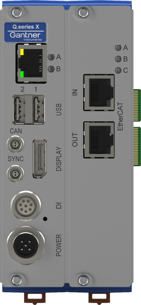
- "A" ("blue")
- ON: system is running
- flashing (200ms): module in configuration mode (break command has been detected)
- "B" ("green")
- EtherCAT interface state controlled by "ET1100"
- OFF: "INIT" state
- flashing (200ms): "PRE-OP" state
- flashing (200ms ON, 1000ms OFF): "SAVE-OP" state
- ON: "OP" state
- "C" ("red/green")
- green: channels configured and are working in their range
- red: at least one analogue channel has range error
Configuration is not OK
- "A" ("blue")
- flashing "SOS"
- "B" ("green")
- interface state (depending on used interface, see above)
- "C" ("red/green")
- flashing SOS
- possible reasons
- when the configuration in EEPROM on socket/backplane is not the same as the configuration in EEPROM on module
- when the module codes (ModTy, SModTy, CaTy, FuTy) are not the same as in the configuration files