Creating a virtual variable for arithmetics
Available operators
Available functions
System variables
Creating a virtual variable for arithmetics
-
Right-click on Virtual Variables under the Q.station → Add → Append Variables.

-
Enter the number of new variables required and click OK.

-
Double-click the newly created virtual variable to open the settings. In the General section, set the Type to Arithmetic.

-
Navigate to the Formula section, where you can add functions and operators.
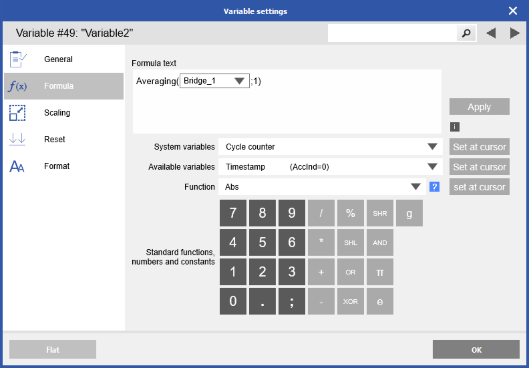
Available operators
- + Addition
- - Subtraction
- * Multiplication
- / Division
- % Modulo
- AND
- OR
- SHL Shift left
- SHR Shift right
- XOR
Available functions
Abs(Value)
Absolute of value
Example: Abs(-243) -> result: 243
ArcCos(Value)
Inverse cosine of value (in radians)
ArcSin(Value)
Inverse sine of value (in radians)
ArcTan(Value)
Inverse tangent of value (in radians)
Averaging(Value;TypeSelector;AdditionalParameter)
Averaging of value
|
0 |
Lowpass filter |
Additional parameter: -3dB filter frequency [Hz] |
|
1 |
Moving |
Additional parameter: number of contiguous data points (N) |
|
2 |
Event-driven reset |
This must be defined in the Event (Reset) section: the most recently stored value is deleted for as long as the condition remains active, ensuring that the value is passed through unaveraged. |
|
3 |
North step |
This is required to eliminate the “north step” problem, which occurs when averaging values across the 0°/360° boundary. This must be defined in the Event (Reset) section: the most recently stored value is cleared while the condition is active, ensuring the value remains unaveraged during this period. |
|
4 |
Arithmetic mean |
Additional parameter: total number of values |
ClassifyValue(TypeSelector;Value)
Averaging of value
|
0 |
Valid |
NOT(Infinite) AND NOT(Not A Number) |
|
1 |
Invalid |
Infinite OR Not A Number |
|
2 |
Normal |
NOT(Infinite) AND NOT(Not A Number) AND NOT(Value 0) |
|
3 |
Not A Number |
|
|
4 |
Infinite |
ControlFFTProcessor(ProcessorIndex)
This function is used to control the internal FFT processors (enable/disable). The condition is taken from the variable’s Event mechanism. Each FFT processor is enabled if it is configured and not controlled by this function.
ResultValue contains information derived from ErrorActive, FunctionDisabled, State, and ExecutionCounter.
-
StateField = ResultValue % 10000
-
ErrorActive = StateField < 0
-
FunctionDisabled = Abs(StateField) >= 1000
-
State = Abs(StateField) % 1000
-
|
0 |
Init |
|
1 |
CheckAndReConfigure |
|
2 |
WaitForData |
|
3 |
ProcessData |
|
4 |
EvaluateData |
|
5 |
EndCycle |
-
ExecutionCounter = Trunc(Abs(ResultValue / 10000))
-
Counts each loop and runs from 0 - 99999 with wrapping
-
ControlFFTProcessorEvaluator(ProcessorIndex;EvaluatorIndex)
This function is used to control the internal FFT Processor Evaluator (enable/disable). The condition is taken from the variable’s Event mechanism. Each FFT Processor Evaluator is enabled if it is configured and not controlled by this function.
ResultValue contains information derived from ErrorActive, FunctionDisabled, State, and ExecutionCounter.
-
StateField = ResultValue % 10000
-
ErrorActive = StateField < 0
-
FunctionDisabled = Abs(StateField) >= 1000
-
State = Abs(StateField) % 1000
-
| 0 | Done |
| 1 | Busy |
-
ExecutionCounter: Counts each loop and runs from 0 - 99999 with wrapping; Trunc(Abs(ResultValue / 10000))
ControlInternalLogger(CommandSelector;LoggerIndex0[;LoggerIndex 1- LoggerIndex n-1])
This function is used to manage the behavior of the internal data logger and is triggered by events.
|
0 |
Enable/Disable |
If the event condition is true, logging is enabled; otherwise, it is disabled. If this function is not used, the logger operates according to its configured activation settings. |
|
1 |
Clear errors |
If the event condition is true, all stored error messages for this logger are cleared. |
|
4 |
Eject drive |
This will eject the current data drive of the logger. The drive can be safely removed once the RUN/LOG LED stops flashing rapidly. |
-
LoggerIndex0[;LoggerIndex 1 … LoggerIndex n-1]: Specifies the Logger index/indices to be used (-1 will select all loggers)
Cos(value)
Cosine of value (in radians)
ConvertDateTimeToTimeOLE2(YYYY;MM;DD;HH;MM;s;ms[;μs])
Converts date and time to OLE Automation (OLE2) date format.
Example: ConvertDateTimeToTimeOLE2(2006;09;01;16;30;25;10)
ConvertDateTimeToTimeDC(YYYY;MM;DD;HH;MM;s;ms[;μs])
Converts date/time to EtherCAT Distributed Clock (DC) time format
Example: ConvertDateTimeToTimeDC(2006;09;01;16;30;25;10)
ConvertTimeDCToDateTime(TimeDC;PartSelector)
Converts EtherCAT Distributed Clock (DC) time format to the corresponding date or time component.
|
0 |
Year |
|
1 |
Month |
|
2 |
Day |
|
3 |
Hour |
|
4 |
Minute |
|
5 |
Second |
|
6 |
Millisecond |
|
7 |
Microsecond |
ConvertTimeOLE2ToDateTime(TimeOLE2;PartSelector)
Converts OLE2 time format to the corresponding date or time component.
|
0 |
Year |
|
1 |
Month |
|
2 |
Day |
|
3 |
Hour |
|
4 |
Minute |
|
5 |
Second |
|
6 |
Millisecond |
|
7 |
Microsecond |
DataLoggerState(LoggerIndex;InfoSelector)
This function retrieves the current status of a specific data logger and can be used to implement a state machine, for example to trigger an email notification in the event of an error.
|
0 |
Error State |
Bit0 = Configuration error Bit1 = Buffer overrun Bit2 = Data limit reached Bit3 = Renaming file failed Bit4 = Creating file failed Bit5 = No storage destination available Bit6 = Sending mail failed Bit7 = Sending a file via FTP failed |
|
1 |
IsEnabled |
The logger is enabled |
|
2 |
IsLogging |
The logger is writing to a file |
|
3 |
IsStartTriggerActive |
The start trigger is in progress |
|
4 |
IsStopTriggerActive |
The stop trigger is in process |
|
5 |
FilesStored |
Number of logged files since the start [times] |
|
6 |
FileProgress |
Progress of the actual file [%] |
|
7 |
TriggerProgress |
Progress of the actual trigger [%] |
|
8 |
MailsSent |
Number of emails sent since the start [times] |
|
9 |
FTPSent |
Number of files sent via FTP |
|
10 |
DestinationIndex |
Index of the actual data storage |
|
11 |
DestinationSize |
Size of the actual data storage [bytes] |
|
12 |
DestinationRemaining |
Available size on the actual data storage [bytes] |
|
13 |
DestinationLoad |
Load of the actual data storage [%] |
|
14 |
DataSrcOverrunCount |
Number of data source overruns [times] |
|
15 |
DataSrcActSize |
Actual size of source data buffer [bytes] |
|
16 |
DataSrcCapacity |
The capacity of source data buffer [bytes] |
|
17 |
DataSrcMaxSize |
Maximum Size of source data buffer since the start [bytes] |
|
18 |
PostProcessBufferSrc |
Number of PostProcessor source overruns [times] |
|
19 |
PostProcessBufferSrc |
Actual size of PostProcessor source data buffer [bytes] |
|
20 |
PostProcessBufferSrc |
Capacity of PostProcessor source data buffer [bytes] |
|
21 |
PostProcessBufferSrc |
Max. size of PostProcessor source data buffer since the start [bytes] |
DeadBand(Value;RangeMinimum;RangeMaximum;TypeSelector;AddParam1;AddParam2)
Suppress a defined range within a variable’s measurement range. Type selector with corresponding additional parameters that define the behavior when (Value ≥ RangeMinimum) AND (Value < RangeMaximum).
|
0 |
Stay at last valid value for duration time, then actual value, |
|
1 |
Stay at last valid value for duration time, then default value, |
|
2 |
Default value for duration time, then actual value, |
Example: Deadband(Var(“xyz”);361;999999;0;1)
The result remains at the last valid value for 1 second. Only if variable "xyz" is greater than 360 for more than 1 second will the actual value of the variable be used again.
Derivative(Value;Timebase)
This function calculates the derivative using a time base (in seconds), with a frequency defined by the controller’s CPU calculation rate.
Equal(Value1;Value2)
Compares two values: if Value1 = Value2, the result is 1; otherwise, the result is 0.
ExtUartDiag(StartIndex;Count)
Returns a code identifying the faulty slave, which can be used, for example, to trigger an email notification in case of a system error.
-
StartIndex: Each slave in the system is assigned a specific bit, sorted according to the UART and its address. StartIndex specifies the bit number where the diagnostic sequence should begin.
-
Count: Specifies the number of slaves to be analyzed. The maximum value depends on the function’s data format (8-, 16-, 32-, or 64-bit). For easier interpretation in large systems, create multiple functions that monitor smaller groups of slaves and adjust the StartIndex for each group. For example: for 16 slaves, use ExtUartDiag(0;8) to check the first 8 slaves and ExtUartDiag(8;8) for the next 8.
FFTProcessor(VariableIndex;Size;WindowType;WindowSubType;WindowParameter;
EnableGeneratingFiles[;Mode;TimeDomainBufferOverlappingPercentage])
Calculates the FFT (Fast Fourier Transform) of an input variable.
-
VariableIndex: The index of the input variable stored in at least one data buffer. Timestamp variables cannot be used. Valid range: 0 - (variable count –1).
-
Size: The number of points to be calculated. Must be a power of 2. Each point requires 52 bytes of internal memory for computation. Valid range: 4 - 1,048,576.
-
WindowType: Weighting functions applied to time-domain signals to minimize spectral leakage that occurs when analyzing a non-integer number of signal cycles.
| 0 |
Blackman |
| 1 |
BlackmanNuttal |
| 2 |
BlackmanHarris |
| 3 |
BartlettHanning |
| 4 |
Exponential or Poisson |
| 5 |
FlatTop |
| 6 |
Gaussian |
| 7 |
Hamming |
| 8 |
Hanning |
| 9 |
Kaiser |
| 10 |
Lanczos |
| 11 |
Nuttal |
| 12 |
PowerOfCosine |
| 13 |
Rectangular or None |
| 14 |
Triangular or Bartlett |
| 15 |
Welch |
-
WindowSubType: Specifies the window sub-type variant, where '0' corresponds to variant 0 and 1 corresponds to variant 1.
-
WindowParameter: Specifies the parameter variants for the selected window function.
|
Exponential or Poisson |
Variant 0 |
Tau [s] |
|
Gaussian |
Variant 0 |
Sigma |
|
Kaiser |
Variant 0 |
Alpha |
|
PowerOfCosine |
Variant 0 |
Power |
-
EnableGeneratingFiles: Controls the generation of files within the controller. These files can be accessed in FTP measurement mode at the root path: tmp/fft.
| SubPath/File | Description |
|
FFTProcessor_Index[i]/ |
Each processor has a subdirectory labeled with its index [i] |
|
sig_reim.dat |
Real/imaginary component of the input signal being used |
|
win_reim.dat |
Real/imaginary component of the window being used |
|
out_maph.dat |
Magnitude/phase of calculated spectrum |
|
[FFTPrEv]analyzed.dat |
The magnitude of the analyzed signal is divided into variables—Original, ZeroOneBin, Zero, Signal, Noise, Distortion, HighestSidePeakInclDistortion, and HighestSidePeakExclDistortion—with filenames prefixed by “FFTProcessorEvaluator_Index[i]_” when multiple evaluators access the same FFT processor for identification. |
-
Mode: Specifies the mode variant; 0 disables signal peak calculation (default), and 1 enables signal peak calculation.
-
TimeDomainBufferOverlappingPercentage: Specifies the percentage of “old” values retained in the time-domain buffer. For example, if set to 75, 75% of the points remain and the oldest 25% are removed. Setting 100 is not allowed, as no new points would be added—maximum is 99. The system attempts to retain all values; if not possible, it switches to “take last defined point count values” mode, which requires less performance but may lose data. Setting 0 (default) removes 100% of the oldest points, producing behavior similar to recent versions.
Calculates values based on the result of a previously defined FFTProcessor.
-
FFTProcessor: Specifies the variable of the FFT processor to be used (V1 - Vn).
-
Function: Specifies the type of FFT evaluator.
|
0 |
FFTErrorStates |
|
1 |
Minimum |
|
2 |
Maximum |
|
3 |
Integral |
|
4 |
RMS (Root Mean Square) |
|
5 |
SINAD (1) (Signal-to-Interference ratio including Noise And Distortion) |
|
6 |
ENOB (1) (Effective Number Of Bits) |
|
7 |
SNR (1) (Signal-to-Noise Ratio) |
|
8 |
THD (Total Harmonic Distortion) |
|
9 |
SFDR (Spurious Free Dynamic Range) |
|
10 |
EVV (Effective Vibration Velocity) |
|
11 |
EVD (Effective Vibration Displacement |
|
14 |
Difference |
|
1000 |
Time Domain Buffer Lossless And Overlapping Health |
(1) Optimized using a Hanning window. Note that single-sine-tone signal sources may produce higher quality than expected, and the signal level should span the full range of the input.
-
StartFrequency: Frequency at which the evaluation begins.
Range: 0.0 - (NyquistFrequency − BinFrequency) and less than StopFrequency. -
StopFrequency: Frequency at which the evaluation ends.
Range: 0.0 - (NyquistFrequency − BinFrequency) and greater than StartFrequency. -
Result1VariableIndex: Index of the output variable where the first result will be written. The variable must have write access. Range: 0 - (number of variables − 1).
| FFTErrorStates | Bit0 = Runtime_ProcessorInputVaribaleIndexError Bit1 = Runtime_ProcessorSizeError Bit2 = Runtime_ProcessorWindowTypeError Bit3 = Runtime_ProcessorWindowSubTypeError Bit4 = Runtime_ProcessorWindowParameterError Bit5 = Runtime_ProcessorEnableGeneratingFilesError Bit6 = Runtime_ProcessorBufferSizeError Bit7 = Runtime_ModeError Bit8 = Runtime_TimeDomainBufferOverlappingPercentageError Bit9 = Runtime_PerformanceSavingTakeLastValuesModeActivatedError Bit10-19 = not used Bit20 = Runtime_ProcessorEvaluatorFunctionError Bit21 = Runtime_ProcessorEvaluatorStartFrequencyError Bit22 = Runtime_ProcessorEvaluatorStopFrequencyError Bit23 = Runtime_ProcessorEvaluatorResult1VariableIndexError Bit24 = Runtime_ProcessorEvaluatorResult2VariableIndexError Bit25-62 = not used Bit63 = Runtime_NotSpecified |
|
Minimum |
Value amplitude [unit of source variable] |
|
Maximum |
Value amplitude [unit of source variable] |
|
Difference |
Value magnitude/amplitude [unit of source variable] |
|
Integral |
Value [unit of source variable] |
|
RMS |
Value [unit of source variable] |
|
SINAD |
Value [dB] |
| ENOB | Value [bits] |
| SNR | Value [dB] |
| THD | Value [dB] |
| SFDR | Value including harmonic distortions of the signal [dB] |
| EVV | Value [m/s] (calculated from a source of VibrationAcceleration [m/s²]) |
| EVD |
Value [m] (calculated from a source of VibrationAcceleration [m/s²]) |
| Others |
Value |
-
Result2VariableIndex: Specifies the index of the output variable where the second result will be written. The variable must have write access.
Range: 0 - (variable count – 1).
|
Minimum |
Value frequency [Hz] |
|
Maximum |
Value frequency [Hz] |
|
Difference |
Value phase [°] |
|
SFDR |
Value excluding harmonic distortions of the signal [dB] |
GetBufferSizePercent(BufferIndex)
This function gets the buffer size [%]
-
BufferIndex: Specifies the index of the buffer to be monitored.
GetPositioningData(Selector;InfoSelector)
Read values from NMEA devices or Garmin GPS.
-
Selector: Specifies the port to which the device is connected (e.g., a GPS module connected via a USB-to-RS232 converter using the NMEA-0183 protocol).
| Code | Port | Description |
| 100 |
USB0 |
Right port |
| 101 |
USB0 Hub-Port0 |
Right port |
| 102 |
USB0 Hub-Port1 |
Right port |
| 103 |
USB0 Hub-Port2 |
Right port |
| 104 |
USB0 Hub-Port3 |
Right port |
| 200 |
USB1 |
Left port |
| 201 |
USB1 Hub-Port0 |
Left port |
|
202 |
USB1 Hub-Port1 |
Left port |
|
203 |
USB1 Hub-Port2 |
Left port |
|
204 |
USB1 Hub-Port3 |
Left port |
|
Code |
Information |
Description |
Device / Command |
|
0 |
Time |
OLE2 (days since 01.01.1900) |
Garmin GPS / |
|
1 |
Latitude |
Degrees (°) and minutes (') |
Garmin GPS / |
|
2 |
Longitude |
Degrees (°) and minutes (') |
Garmin GPS / |
|
3 |
Speed |
[m/s] |
Garmin GPS / RMC |
|
4 |
Heading |
[°] (0° = North, 90° = East, |
Garmin GPS / RMC |
|
5 |
Number of satellites |
|
Garmin GPS / GSV, GGA |
|
6 |
Altitude above NN |
[m] |
Garmin GPS / GGA |
|
7 |
Quality |
state (0 = invalid, 1 = GPS, |
GGA |
|
8 |
Horizontal dilution of precision |
GGA |
|
|
9 |
Rate and direction of turn |
ROT |
|
|
10 |
Longitudinal water speed |
|
VBW |
|
11 |
Transverse water speed |
|
VBW |
|
12 |
Longitudinal ground speed |
|
VBW |
|
13 |
Transverse ground speed |
|
VBW |
|
14 |
Track degrees: true |
|
VTG |
|
15 |
Track degrees: magnetic |
|
VTG |
|
16 |
Depth below transducer |
[feet] |
DBT |
|
17 |
Depth below transducer |
[m] |
DBT |
|
18 |
Depth below transducer |
[fathom] |
DBT |
|
19 |
Water: depth |
[m] |
DPT |
|
20 |
Water: offset from transducer |
|
DPT |
|
21 |
Wind: angle |
[°] |
MWV |
|
22 |
Wind: speed |
|
MWV |
|
23 |
Water: temperature |
[°C] |
MTW |
|
24 |
Own ship data: heading |
[°] |
OSD |
|
25 |
Own ship data: vessel course |
[°] |
OSD |
|
26 |
Own ship data: vessel speed |
|
OSD |
|
27 |
Own ship data: vessel set |
[°] |
OSD |
|
28 |
Own ship data: vessel drift |
|
OSD |
|
29 |
RADAR data: cursor range |
|
RSD |
|
30 |
RADAR data: cursor bearing |
[°] |
RSD |
|
31 |
RADAR data: range scale |
|
RSD |
|
32 |
Heading degrees: true |
[°] |
HDT |
|
33 |
Speed |
[knots] |
VTG |
|
34 |
Speed |
[km/h] |
VTG |
|
35 |
Latitude |
Decimal [°] |
GGL, GGA |
|
36 |
Longitude |
Decimal [°] |
GGL, GGA |
|
100 |
Error states |
state (0 = invalid char format, 1 = invalid baud rate, 2 = invalid port config, |
|
Conversion of Latitude/Longitude:
- XXYY.ZZZZ ⇒ XX° + (YY.ZZZZ / 60)°, or
- XXYY.ZZZZ ⇒ XX° YY’ (0.ZZZZ * 60)’’
GetSystemHealth(Selector)
Returns controller health status.
| 0 |
Actual System health |
[%] |
| 1 |
Actual Real-time health |
[%] |
| 2 |
Average System health |
[%] |
| 3 |
Average Real-time health |
[%] |
High(Arg1;Arg2[;Arg3;Arg4])
Returns the maximum value among multiple arguments.
Example: High(35;21;46) = result: 46
Higher(Arg1;Arg2)
Returns the result of the comparison Arg1 > Arg2.
Example:
Higher(35;42) -> result: 0
Higher(35;23) -> result: 1
HigherEqual(Arg1;Arg2)
Returns the result of the comparison Arg1 >= Arg2
Example:
HigherEqual(35;35) -> result: 1
HigherEqual(17;35) -> result: 0
Highest(Arg1;Arg2[;Arg3;Arg4])
Returns the maximum value among multiple arguments.
Example: Highest(17;12;43;8) -> result: 43
Integrator(Value)
This function calculates the integrated value; the input is evaluated and integrated at the processing interval defined by the controller’s CPU calculation rate.
Create an enhanced stream under the Q.station and select the variable to be analyzed. Then create an arithmetic virtual variable under the enhanced stream and add the Integrator function.
Ln(Value)
Returns the natural logarithm (base 𝑒) of the value.
Log(Value)
Returns the base-10 logarithm of the value.
Low(Arg1;Arg2[;Arg3;Arg4])
Returns the minimum value among multiple arguments.
Example: Low(35;21;46) = result: 21
Lower(Arg1;Arg2)
Returns compare result of Arg1 < Arg2
Example:
Lower(12;17) -> result: 1
Lower(23;17) -> result: 0
LowerEqual(Arg1;Arg2)
Returns compare result of Arg1 <= Arg2
Example:
LowerEqual(17;17) -> result: 1
LowerEqual(17;12) -> result: 0
Max(Value)
The maximum value is stored and must be reset when required. To reset this result, configure the settings in the Reset tab. The available reset options depend on the location of the arithmetic variable.
Min(Value)
The minimum value is stored and must be reset when required. To reset this result, configure the settings in the Reset tab. The available reset options depend on the location of the arithmetic variable.
Not(Value)
Returns the bitwise inverted value.
PIDControllerIndexBased(ReferenceValue;ActualValue;ProportionalPart;IntegralTime;DerivativeTime;Mode;TimeBase;OutputVariableWriteAccessIndex + 1[;Type])
This function provides PID controller functionality.
No enable/disable events are supported. Turning control on or off is only possible using the Mode parameter. If the Host event is enabled, the output value can be set while the control loop is open.
-
ReferenceValue: Command value, also known as the setpoint value or 𝑤.
-
ActualValue: Feedback value, also known as the process value or 𝑥.
-
ProportionalPart: Proportional gain (Kp), also called the P-contribution.
-
IntegralTime [s]: Integral time (Ti), also called the I-contribution.
-
DerivativeTime [s]: Derivative time (Td), also called the D-contribution.
-
Mode:
-
Bit0: ControlLoopClosed, enables configuration of the control loop (default).
-
Bit 1: OutputLimitationDisabled, enables configuration of output limitation (default) to a range of ±1.0.
-
-
TimeBase [s]: Minimum = 1.0 ÷ sample frequency. Select according to the required control loop speed, keeping in mind that a slower control speed reduces CPU usage.
-
OutputVariableWriteAccessIndex + 1: Specifies the index of the output variable where the value will be written. Only variables with a data direction of OUTPUT or INPUT/OUTPUT can be used.
-
[Type]: Optional parameter to define type of controller
-
1 : D-contribution based on derivative of process value (𝑥)
-
Power(Base;Exponent)
Returns the powered value (Result = BaseExponent).
Example: Power(2;3) -> result: 8
Random(LimitValue)
Returns a random integer value. The Limitvalue must be greater than 1; the result will then be in the range 1 … LimitValue.
RoundToValue(Value;RoundToValue)
This function rounds a value to the decimal place specified by RoundToValue.
Example:
RoundToValue(5,0537;1) -> result: 5
RoundToValue(5,0537;10) -> result: 10
RoundToValue(5,0537;0,001) -> result: 5,054
Select(SelectorValue;ValueForSelectorValueEquals0[;ValueForSelectorValueEquals1;...;ValueForSelectorValueEquals7])
Returns a value determined by the SelectorValue.
-
SelectorValue: The selector value, converted to an integer, is used as the index for the following value list. If the index is not present, the last value in the list is used.
-
ValueForSelectorValueEquals0-7: The value selected when the integer-cast SelectorValue matches its index.
Example:
Select(1;1;2;3) -> result: 2
Select(7;1;2;3) -> result: 3
Select(-1;1;2;3) -> result: 3
SelectSystem(SystemValueSelector;AddParam)
Returns the system performance indicators.
|
Code |
Meaning |
Description |
AddParam |
|---|---|---|---|
|
0 |
EtherCAT cycle counter(1) |
uint64_t |
Not used (0) |
|
1 |
EtherCAT async buffer content counter(1) |
uint64_t |
Value identifier |
|
2 |
Controller temperature(3) |
[°C] |
Sensor index |
|
3 |
Controller supply voltage(3) |
[V] |
Sensor index |
|
4 |
Calculation rate |
[Hz] |
Not used (0) |
|
5 |
System health |
0-100% |
Not used (0) |
|
6 |
Free memory |
[%] |
Not used (0) |
|
OnlineDataPort |
|||
|
100 |
OnlineDataPort_SumActivityBitset(2) |
Bitset for all port activity |
Not used (0) |
|
101 |
OnlineDataPort_ActiveCount(2) |
No. of active ports |
Not used (0) |
|
102 |
OnlineDataPort_InactiveCount(2) |
No. of inactive ports |
Not used (0) |
|
103 |
OnlineDataPort_EventBitset(2) |
Bitset for all port events |
Port Index |
|
104 |
OnlineDataPort_MsSinceLastTransfer(2) |
Value for specified port |
Port Index |
|
|
DataStream |
||
|
200 |
DataStream_SumActivityBitset(2) |
Bitset for stream activity |
Not used (0) |
|
201 |
DataStream_ActiveCount(2) |
No. of active streams |
Not used (0) |
|
202 |
DataStream_InactiveCount(2) |
No. of inactive streams |
Not used (0) |
|
203 |
DataStream_EventBitset(2) |
Bitset for stream events |
Port Index |
|
204 |
DataStream_MsSinceLastTransfer(2) |
Milliseconds since last transfer for stream |
Port Index |
|
205 |
DataStream_ActBandwidthMBSec(2) |
Actual bandwidth [MB/s] |
Port Index |
|
206 |
DataStream_HandledDataMB(2) |
Amount of handled data since start [MB] |
Port Index |
|
207 |
DataStream_LastTransferSize(2) |
No. of bytes received at last transfer |
Port Index |
|
208 |
DataStream_BufferedSizeMB(2) |
Available size [MB] |
Port Index |
|
209 |
DataStream_Load(2) |
Used capacity [0-100%] |
Port Index |
|
210 |
DataStream_AvailableTimeRange(2) |
Not working yet |
Port Index |
|
211 |
DataStream_LastTransferEpochSec(2) |
Absolute time of last transfer since epoch [s] |
Port Index |
|
Miscellaneous |
|||
|
600 |
GIcom_ThreadPoolStatus(2) |
ThreadPool status of GI.com |
0 = allocated |
(1) Only available on Q.pac EC
(2) Only available with project objects
(3) Not supported by Q.monixx controllers, use this function at the module level instead.
SendMailToMailServer(AddressIndex;SubjectIndex;BodyIndex;WithDataFile;BufferIndex;DataDriveIndex;FileIdent;FileRepeatIndex;DeleteAfterSend;IsBlocking)
This function allows sending an email.
Attaching a data file with this function is no longer supported on Q.station and Q.monixx controllers. Use the logger functionality to send data files via email instead.
-
AddressIndex: Up to 10 email addresses can be defined in the controller. The index ranges from 0 - 9, corresponding to email address 1 - 10. If -1 is specified, the message will be sent to all defined email addresses.
-
SubjectIndex: Up to 10 email subjects can be defined in the controller. The index ranges from 0 - 9, corresponding to email subject 1 - 10.
-
BodyIndex: This is the email body text defined in the controller. The index ranges from 0 - 9, corresponding to email body text 1 - 10.
-
WithDataFile: No longer used; leave set to 0.
-
DataDriveIndex: No longer used; leave set to 0.
-
FileIdent: No longer used; leave set to 0.
-
FileRepeatIndex: No longer used; leave set to 0.
- DeleteAfterSend: No longer used; leave set to 0.
- IsBlocking:
-
0: No, the main program loop does not wait for the function to finish. Finalization should be detected using the resulting state (recommended).
-
1: Yes, the main program loop will wait for the function to finish.
-
-
ResultValue:
This function is event-driven, it is triggered while the event condition is active. Ensure the event is active for only one cycle, so that only one email per event is sent.
|
0 |
Ready, OK |
|
1 |
DestinationAddressIndexError |
|
2 |
SubjectIndexError |
|
3 |
BodyIndexError |
|
4 |
CreateError |
|
5 |
SetDomainError |
|
6 |
AuthenticateSendServerError |
|
7 |
AuthenticatReceiveServerError |
|
8 |
PrepareNewMediaError |
|
9 |
SetDestinationAddressError |
|
10 |
SetAttachmentError |
|
11 |
SetSignatureError |
|
12 |
SrcFileNotFoundError |
|
13 |
ScrFileDeleteError |
|
200-250 |
Internal Error |
|
500 |
Busy |
|
501 |
SendMailInitInProgress |
|
502 |
SendMailInProgress |
|
503 |
ReceiveMailInitInProgress |
|
504 |
ReceiveMailInProgress |
|
1001 |
NotRunning |
Sin(Value)
Returns the sine of a value in radians.
Example:
Sin(0.5) -> result: 0.479
Sin(0.5∗π)-> result: 1
Sin(90°∗π/180) -> result: 1
Sqr(value)
Returns the square of a value.
Example: Sqr(4) = 16
Sqrt(value)
Returns the square root of a value.
Example: Sqrt(25) = 5
State(Selector)
This function retrieves the current state of the entire system.
- Selector:
- 0: GeneralStates
- 1: RunStates
- 2: ErrorStates
|
Selector |
Bit |
Description |
|
GeneralStates |
Bit0 |
InitActive |
| RunStates |
Bit0 |
HostConfigBusRS485Active |
|
ErrorStates |
Bit0 |
ConfigFileError |
StdDeviation(Value)
Returns the standard deviation of a value (event-driven function).
-
Formula:


The final value of n (total number of samples to sum) is unknown during formula execution. n equals the number of samples between two event conditions.
The summation values in the formula are stored as 64-bit double. Depending on n × (size of the measurement value), an overflow may occur.
SystemControl(CommandSelector)
Allows handling of certain system actions (event-driven function).
-
CommandSelector:
-
0: Removes error messages in Q.station shown as user information
-
1: Restart device
-
2: EjectDataStorage (not implemented yet)
-
3: Set display backlight (use event condition to enable/disable; Param value: 0–100%)
-
When using “Restart device”, if the event is already true (1) at system boot, the controller will enter a restart loop. Verify the event condition carefully when configuring this function.
Tan(Value)
Returns the tangent of a value in radians.
ThCou(Mode;Type;ThermocoupleVoltageValue;ReferenceTemperatureValue)
Calculates temperature using a thermocouple algorithm.
-
Mode: Encodes information from ModeNumber and ModeBitset as: Mode = ModeBitset × 100 + ModeNumber
|
Bit0 |
DoIncludeErrorValues |
An error offset is added to ResultValue when an error occurs: |
|
Bit1 |
AllowExtrapolation |
Out-of-range values are extrapolated. |
|
0 |
Full calculated thermocouple value |
[°C] |
|
1 |
Intermediate ReferenceTemperatureValue as voltage value |
[V] |
|
2 |
Intermediate ThermocoupleVoltageValue added with ReferenceTemperatureValue as voltage value |
[V] |
-
Type: Indicates the thermocouple type according to IEC 584, which is equivalent to ASTM E230, BS 4937, ANSI MC96.1, and NF C 42-324.
|
0 |
Thermocouple Type B |
|
10 |
Thermocouple Type C |
|
1 |
Thermocouple Type E |
|
2 |
Thermocouple Type J |
|
3 |
Thermocouple Type K |
|
4 |
Thermocouple Type L |
|
5 |
Thermocouple Type N |
|
6 |
Thermocouple Type R |
|
7 |
Thermocouple Type S |
|
8 |
Thermocouple Type T |
|
9 |
Thermocouple Type U |
-
ThermocoupleVoltageValue: Measured thermocouple voltage value [V]
- ReferenceTemperatureValue: Fixed or measured reference temperature value [°C]
This functions returns the true RMS value.
| 0 | Lowpass filter fade out |
| 1 |
Sliding fade out |
| 2 |
Arithmetic mean fade out |
|
Lowpass filter fade out |
Time constant Tau [s] |
|
Sliding fade out |
Buffer depth |
|
Arithmetic mean fade out |
Weighting number |
If only two parameters are set, a low-pass filter is activated, and the second parameter is used as the time constant (𝜏).
Trunc(Value)
Returns the truncated integer representation of the value.
Example: Trunc(17.689) = 17
ValueChanged(Value[;Type];AdditionalParameter)
Returns whether the value has changed according to specified conditions since the last cycle.
|
Code |
Description |
AdditionalParameter |
|
0 |
Round to value before |
RoundToValue |
|
1 |
Step is greater than CompareValue |
|
|
2 |
Step is lower or equal than CompareValue |
|
|
3 |
Round to value before, event driven reset of result(1) |
|
|
4 |
Step is greater than CompareValue |
CompareValue |
|
5 |
Step is lower or equal than CompareValue |
CompareValue |
(1) Result is set to 0 with event mechanism only
Example:
-
ValueChanged(V3;0.02) -> Returns 1 for one cycle if the value of V3, rounded to 0.02, differs from the previous cycle.
-
ValueChanged(V3;1;0,5) -> Rising edge detection; returns 1 for one cycle if the change in value since the last cycle is > 0.5.
-
ValueChanged(V3;1;-0.5) -> Falling edge detection; returns 1 for one cycle if the change in value since the last cycle is ≤ 0.5.
ValueEvaluation(Value;Type;Time;Value1;Value2)
Turns ON or OFF with a delay when a value exceeds a threshold or enters a defined range (see parameter Type). Hysteresis can also be configured with this function.
|
0 |
High logic (ON delayed) |
|
1 |
Low logic (ON delayed) |
|
2 |
Range detect high (ON delayed) |
|
3 |
Range detect low (ON delayed) |
|
4 |
High hysteresis (ON delayed) |
|
5 |
Low hysteresis (ON delayed) |
|
6 |
Not used |
|
7 |
Not used |
|
8 |
Not used |
|
9 |
Not used |
|
10 |
High logic (OFF delayed) |
|
11 |
Low logic (OFF delayed) |
|
12 |
Range detect high (OFF delayed) |
|
13 |
Range detect low (OFF delayed) |
|
14 |
High hysteresis (OFF delayed) |
|
15 |
Low hysteresis (OFF delayed) |
Var(IDOrName)
This function retrieves the value of a variable.
-
IDOrName: ID or name string, enclosed in quotes ("").
VariableWrite(DestinationVariable;SourceValue)
This function allows writing a value to an output variable.
-
DestinationVariable: The output variable where the value will be written. The variable must be configured as OUTPUT or INPUT/OUTPUT.
- SourceValue: Defines the source value, which can be a constant, setpoint, or another variable.
VariableWriteIndexBased(DestinationVariableWriteAccessIndex + 1;SourceValue)
This function allows writing a value to an output variable using its index.
-
DestinationVariableWriteAccessIndex + 1: Specifies the index of the output variable where the source value will be written. Only variables with a data direction of OUTPUT or INPUT/OUTPUT can be used.
-
SourceValue: Defines the source value, which can be a constant, setpoint, or another variable.
Example:
|
Variable |
Data Direction |
Output Var Index + 1 |
|
V1 – Timestamp |
INPUT |
- |
|
V2 – Setpoint 1 |
INPUT |
- |
|
V3 – Setpoint 2 |
INPUT/OUTPUT |
1 |
|
V4 – Setpoint 3 |
INPUT |
- |
|
V5 – Setpoint 4 |
OUTPUT |
2 |
|
V6 – WriteOutputVar |
INPUT |
- |
|
V7 – SourceValue |
INPUT/OUTPUT |
3 |
-
VariableWriteIndexBased(1;Var(“V7 - SourceValue”)) -> The value of V7 – SourceValue is written to V3 – Setpoint2
-
VariableWriteIndexBased(2;Var(“V7 - SourceValue”)) -> The value of V7 – SourceValue is written to V5 – Setpoint4
System variables
In addition to physical inputs and virtual variables, system variables are available and can be used in arithmetic functions.
Cycle counter
Counts the number of controller cycles since the controller was started (power-up or after writing a new configuration). The duration of one controller cycle is defined by the system sample rate.
Time since start [μs]
Time in microseconds since the controller was started (power-up).
Time since begin of day [s]
Time in seconds since 00:00:00 UTC of the current day, ranging from 0 to 86,399.
Time since begin of hour [s]
Time in seconds since the start of the current hour, ranging from 0 to 3,599.
Time since begin of year 2000 [ns]
Time in nanoseconds since time zero (epoch) of January 1, 2000, 00:00:00 UTC.
Time in OLE2 format
TBD