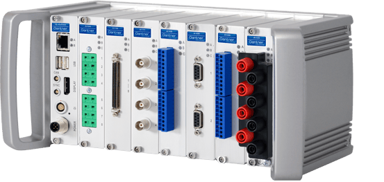
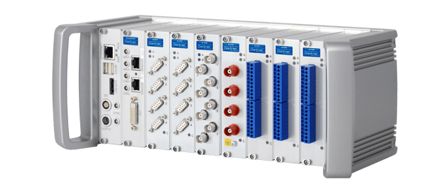
This guide will describe how to put together a Q.brixx (X-series and Classic) system using a test controller (i.e. Q.station) and the measurement modules. To disassemble or replace a module, reverse the procedure.
The Q.brixx 1 and 2 form factors have been discontinued
Form Factor
Tools Required:
- Torx T8 screwdriver
- Phillips screwdriver (for older Q.brixx-X devices)
- 3mm hex key (Q.brixx-X handles) or 2.5 mm hex key (for Q.brixx 1 and 2)
- 2,5mm hex key for sockets (Q.brixx-X)
Procedure (Q.brixx X):
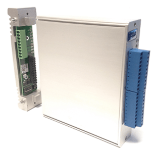
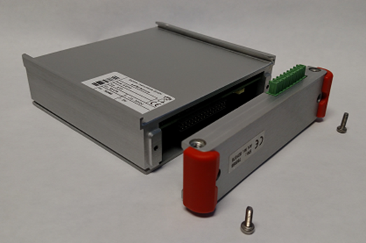
- Each controller and measurement module includes a base. Separate the base from each device by loosening the screws with the Torx screwdriver (use Phillips head screwdriver for older modules). Note that the base for the controller is different from the measurement modules.
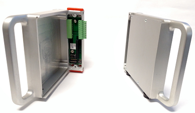
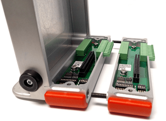
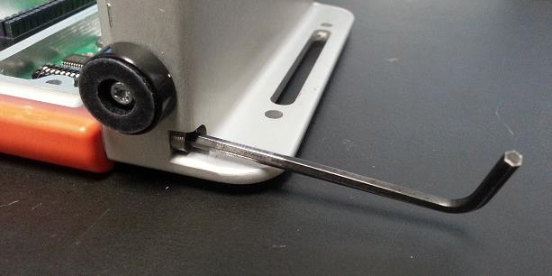
- A Q.brixx X controller is usually paired with 2 handles (left and right side). Attach the controller base to the left handle with the 3 mm hex key.
- Attach the first measurement module base to the controller base with the 3mm hex key.
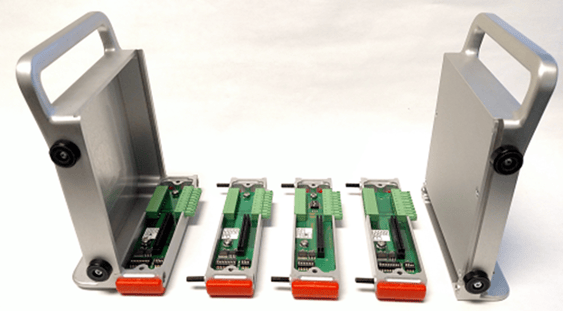
- Attach all the measurement module bases moving from left to right.
- Attach the right handle to the last module base with the 3mm hex key.
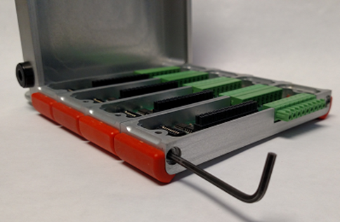
- Set DIP switches in each module for the appropriate UART and if terminating resistors need to be activated. You can also fix the module's address using the DIP switches on the base. See this article for more info: https://knowledge.gantner-instruments.com/q.brixx-base-configuration-dip-switch
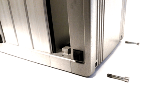
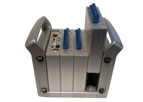
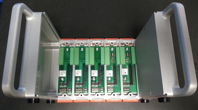
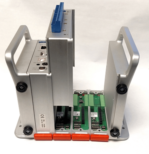
- Insert 2 black plastic inserts on the right side of the Q.station X before placing it on the leftmost position.
- Insert 2 black plastic inserts on the right side of the next measurement module before placing it to the right of the Q.station X. Repeat as needed for the remaining modules.
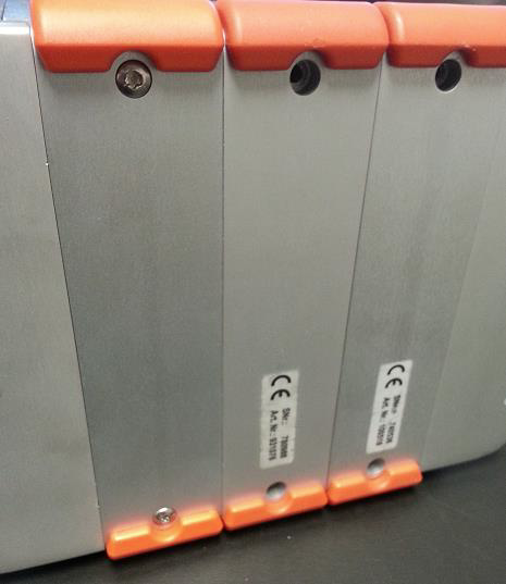
- Tighten each screw on the front of each controller and modules.
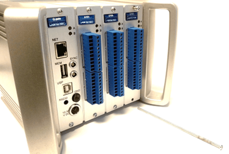
- The assembly is complete. Connect power and Ethernet cable to the front of the Q.station X for initial configuration.
Procedure (Q.brixx 2):
- Each controller and measurement module includes a base. Separate the base from the module by loosening the screws on the front of the device
- A controller in the brixx packaging comes with 2 x handles (left and right sides). Attach the left side handle to the controller’s base.
- Attach all the bases moving from left to right. Secure the bases together using a 2.5 mm hex key (2 x screws):
- Connect the right side handle after all the bases have been attached and secured together. Secure the right side handle using the same 2.5 mm hex key (2 x screws):
- Once all the bases have been secured and the handles are secured, it is time to configure the address for each module. The address is configured on the module's base using the DIP switches. There are 2 sets of DIP switches on a base; using the larger set, set the address using the first 8 switches.
- The controller always has an address of 0. Moving from left to right, set the address in numerical order.
- After all the addresses have been configured, connect the modules from left to right with the controller.
- Secure the modules to the base using screws on the front of each module:
- The Q.brixx assembly and address configuration are complete. The system can be powered on and connected to the PC for internal configuration.
Procedure (Q.brixx 1):
- Each controller and measurement module includes a base. Separate the base from the module by removing the 2 x Torx T10 screws from the back of the base.
- A controller in the brixx packaging comes with 2 x handles (left and right sides). Attach the left side handle to the controller’s base.
- Attach all the bases moving from left to right. Secure the bases together using a 2.5 mm hex key (2 x screws) one at a time:
- Connect the right side handle after all the bases have been attached and secured together. Secure the right side handle using the same 2.5 mm hex key (2 x screws):
- Once all the bases have been secured and the handles are secured, it is time to configure the address for each module. The address is configured on the module's base using the DIP switches. There are 2 sets of DIP switches on a base; using the larger set, set the address using the first 8 switches.
Example:
Address DIP Switch Setting 0 00000000 1 10000000 2 01000000 3 11000000 4 00100000 5 10100000 6 01100000 7 11100000
Key: 1 = UP / 0 = DOWN - The controller always has an address of 0. Moving from left to right, set the address in numerical order.
- After all the addresses have been configured, connect the modules from left to right with the controller.
- Secure the modules to the base using 2 x Torx T10 screws for each module:
- The Q.brixx assembly and address configuration are complete. The system can be powered on and connected to the PC for internal configuration.