To maintain galvanic isolation between the sensor supply, Q.station power supply, and analog inputs, a separate power supply must be provided for the sensor supply.
Connect the power supply to pins 3 and 4 on the Q.station's or bus coupler's front M12 binder power connector.

Figure 1
It is imperative to provide a sensor voltage supply at the M12 connector (power supply connector) of the Q.station or at the rack. This supply must be from a galvanically isolated power source with a maximum rating of 4 A. Please reach out to Gantner Instruments if you require an AC rack.
Here is an example of how to connect a current sensor using the sensor supply:
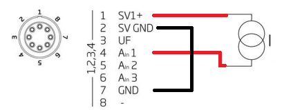
Figure 2
SV Module Variants: A101 SV, A107 SV, D101 SV, D107 SVA101 SV connection details:

A107 SV Connection details:
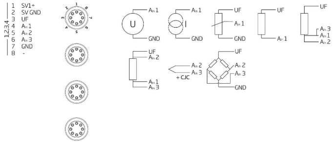 Figure 4
Sensor excitation:
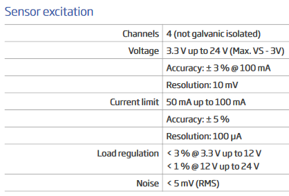
24V is only possible if you connect VS: >= 27V
You can configure that in the module settings (GI.bench or ICP 100).
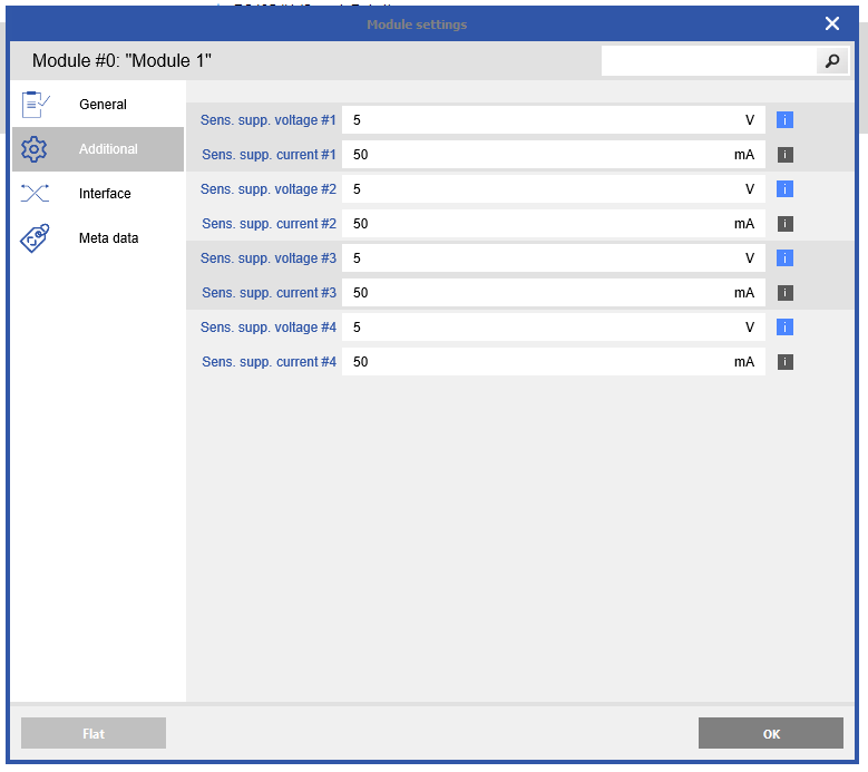
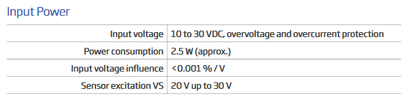
Figure 5
Due to the possible heat build-up of the analog and digital modules, there is a maximum current allowance of 100 mA with the A101/A107 modules and a maximum of 250mA with the D101/D107 modules.
For the datasheet of the A107, please refer to the following link: datasheet.
D101 SV connection details:

Figure 6
D107 SV connection details:

Figure 7
Practical Setup of a Y-Connector
To assemble a Y-connector for the sensor supply, follow these steps:
-
Prepare the Power Supply Lines:
- Carefully strip the insulation from both power supply cables, exposing approximately 6 mm of wire.
- Slide the following components onto both lines in order:
- Position 1: The clamping ring.
- Position 2: The strain relief.
- Position 3: The connector housing.
Refer to Figure 8 for visual guidance.

Figure 8
-
Wiring the M12 5-Pin Connector (Position 4):
- Wire the M12 5-pin connector as shown in Figure 1, ensuring the correct pin configuration.
- Pay careful attention to the insulation between the poles and between the two power supplies to avoid any short circuits or potential interference.
-
Connection of Y-Ends:
- The two ends of the Y-connector can be stripped and connected as required (Position 5.1) as shown in Figure 9. Alternatively, they can be equipped with two M12 5-pin sockets (Pin 1 for +, Pin 2 for -).
- These ends can then be directly connected to two separate power supplies.

Figure 9
This setup allows for safe and effective distribution of the sensor supply while maintaining galvanic isolation. Ensure that all connections are secure, and insulation is sufficient to prevent cross-wiring or electrical faults.