A PWM digital output signal is possible with an A109 or D101 module
Background
A PWM signal is a method for creating digital pulses. The primary components are:
- Duty cycle: Fraction of one period when a signal is activate, expressed as a ratio or percentage. A signal that is on half the time and off half the time has a duty cycle of 50% i.e. square wave.
- Frequency: The rate at which something occurs over a specific period
Configuration
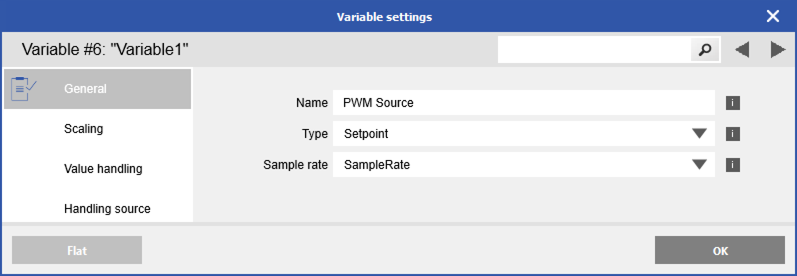
When you select the digital output type of PWM, you will see a scaling, value handling, and source section for the PWM and frequency parts
Source
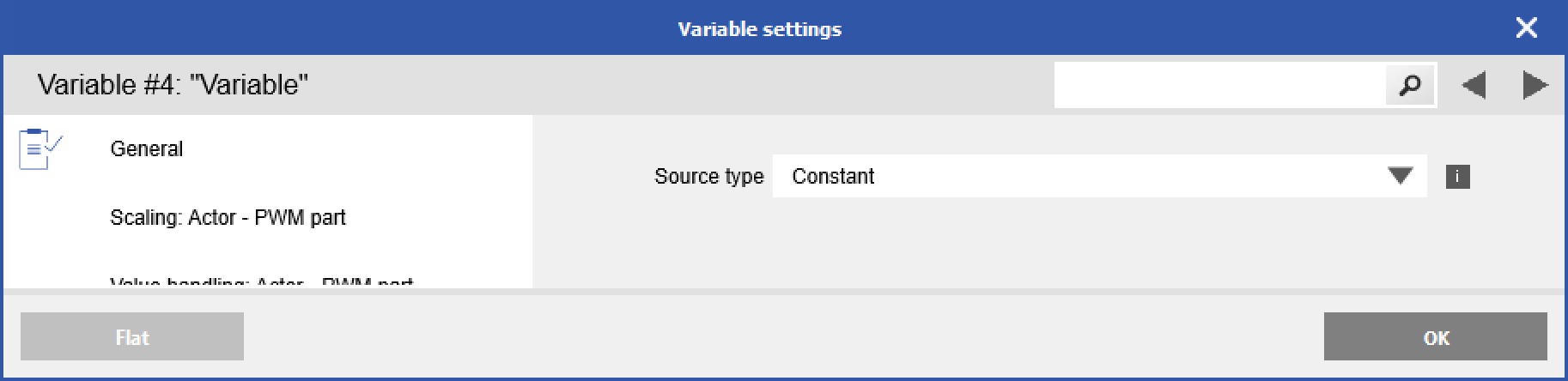
This defines what is the source of the duty cycle parameter (or Frequency if in the "Source: Actor - Frequency part" section). Internal will allow you to select a variable within the same module. External lets you select a variable from another module is the same system. Constant will use the default value as defined in the value handling section.
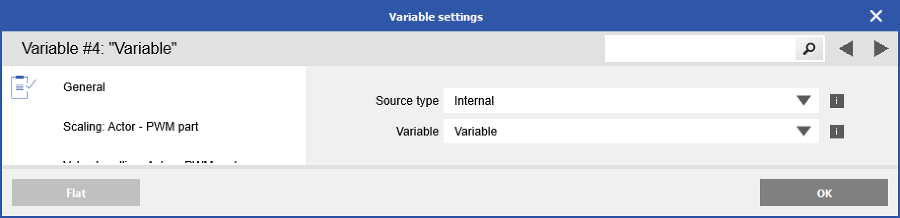
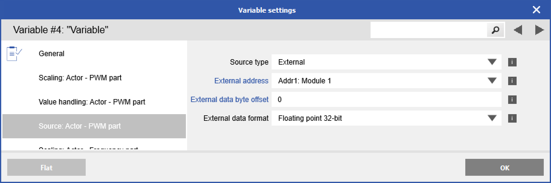
With Internal or External, you can select a Setpoint variable that you can create in the module. A Setpoint in an input/output direction variable that you can use to set a value, to change the duty cycle or frequency in real-time, without the need to reconfigure your system.
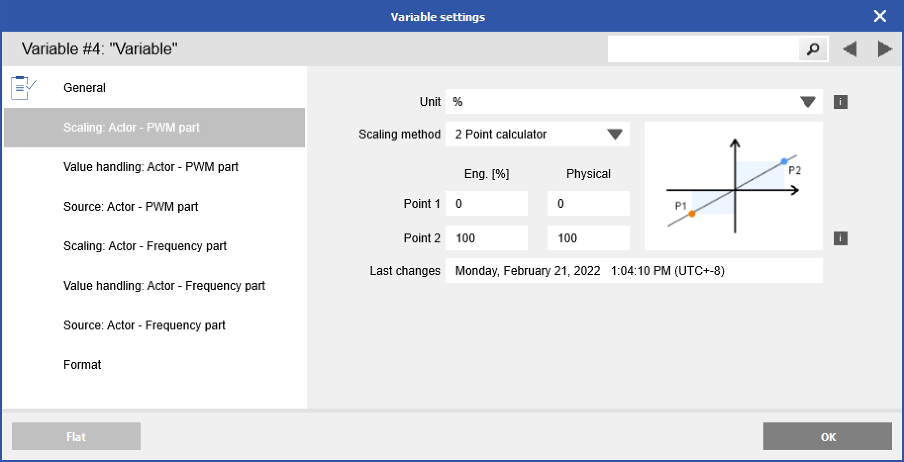
Scaling
Unit for PWM part should be "%". You can scale by Factor and Offset or 2 Point Calculator. This scales between the source and output.
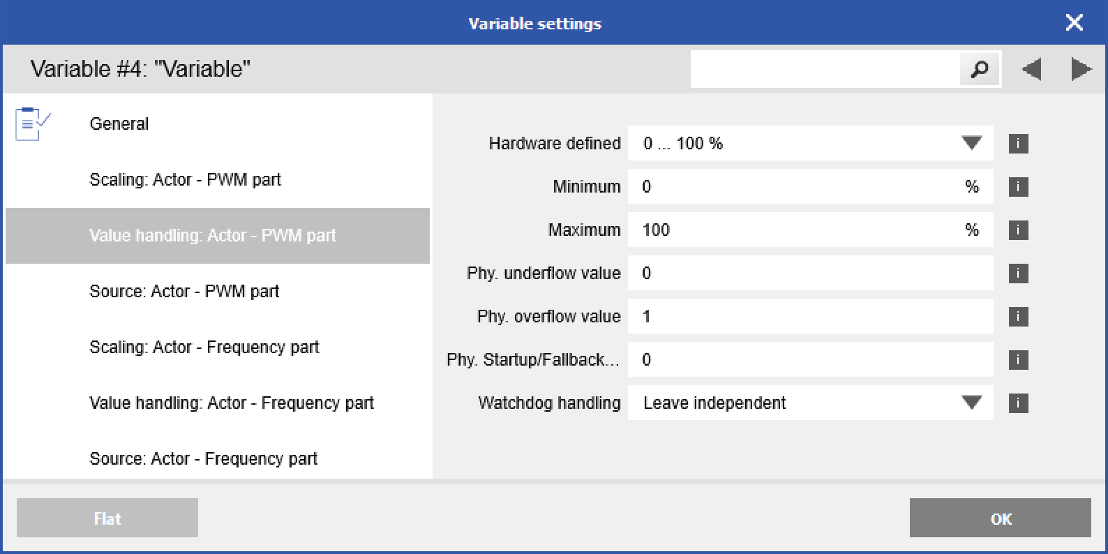
Value Handling
The Phy. Startup/Fallback value is used on startup and if Constant is selected as the source.