Q.bloxx Classic OEM modules
The Q.bloxx A117 OEM is based on a different concept, resulting in variations in both the mechanical interface and electrical connections compared to the standard Q.bloxx OEM modules. Please refer to the downloadable interface drawing for detailed information.
Mechanical installation
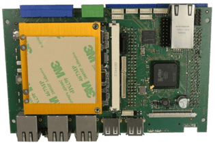
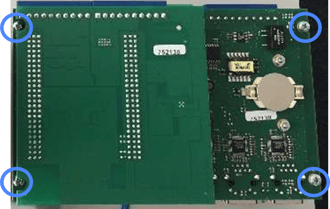
The Q.bloxx Classic OEM modules can be securely mounted using four screws (M3). These modules feature a double-layer PCB board, with the analog component positioned on the top layer and two sets of 10-pole terminals. The CPU board is located at the bottom, complete with a fully functional socket.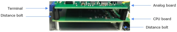
The 3D model of the OEM module in STEP format is available for download from the Gantner Instruments public download area.
Electrical connections
The OEM board facilitates electric connections via JST PH series PCB headers.
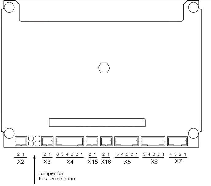
Connector X7 serves as the power supply interface for the module, accommodating voltages in the range of 10-30 VDC.
Connector X3 is used for the RS-485 bus, supporting either Gantner's proprietary Locabus protocol or Profibus.
To daisy-chain multiple modules, use connector X2 to establish the bus connection with the subsequent module. To terminate the bus, connect two jumpers between connectors X2 and X3 on the last module in the bus, as illustrated in the image below.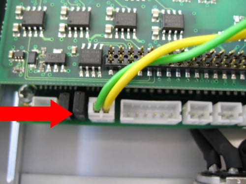
For the RS-485 bus connection, it is recommended to twist the two wires into a pair to minimize external noise interference.
|
X2 |
X3 |
X4 |
|
|
|
|
X15 |
X16 |
X5 |
|
|
|
|
X6 |
X7 |
Jumper |
|
|
|

The information provided above is also accessible in PDF file format.
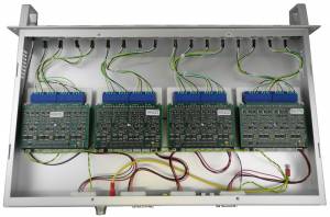
Example of Q.bloxx OEM modules installed in a customized 19-inch rack
Q.station 101 OEM (Classic series)
Mechanical installation
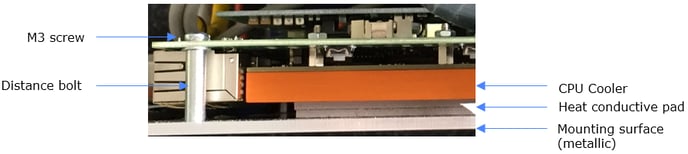
The Q.station 101 can be securely mounted using four M3 screws. The CPU cooler is equipped with a heat conductive pad on the metal surface. To ensure proper support for the heat-conducting pad, use four distance bolts for M3 screws with a length of 20 mm. This ensures a stable and safe mounting configuration.