Introduction
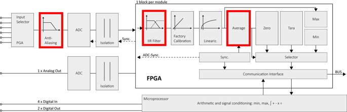
Filtering is a critical aspect in measuring analog signals, serving to enhance the accuracy and reliability of the acquired data. Filtering techniques are applied to selectively allow certain frequencies while attenuating or eliminating others, ensuring that the measured data reflects the true characteristics of the signal of interest. The Q.series measurement modules feature three types of filtering: anti-aliasing filtering, digital filtering, and arithmetic mean filtering.
Anti-aliasing filter
Measurement modules have a fixed sample rate. Ideally, this sample rate should be greater than or equal to 2x the highest frequency component found in the input signal (Nyquist limit). Violating this rule introduces unwanted frequency band signals known as aliasing.
The purpose of the anti-aliasing filter (AAF) is to keep the alias (difference frequency) out of the digitized data. Importantly, the AAF does not affect the module's sampling rate.
For example:
- Module sample rate: 100 kS/s
- Anti-aliasing filter: 20 kHz
In this scenario, the module always samples at 100 kS/s per channel. The role of the filter is to limit the bandwidth to approximately 20 kHz, not the sampling rate.
Digital filters
After passing through galvanic isolation, the measurement modules offer the option to set digital input filters integrated into the FPGA software. These filters operate in conjunction with the internal frequency of the A/D converter. The IIR filters can be configured as low-pass (LPF), high-pass (HPF), band-pass (BPF), and band-stop (BSF). Additionally, they can be configured as a Bessel or Butterworth filter.
The digital filters are based on an IIR (infinite impulse response) transfer function, also known as a recursive filter, and are executed on the measurement module's FPGA. As the filtering takes place after A/D conversion, its purpose is to eliminate noise introduced during the conversion process. The implementation of the IIR filters was guided by 'The Scientist and Engineer's Guide to Digital Signal Processing'.


The standard digital filters are Chebyshev Type I filters, allowing ripple only in the passband. Depending on the module type a Bessel or Butterworth filter (low-pass, high-pass, band-pass, band-stop) can be 2nd, 4th, 6th, or 8th order can be set.
- Butterworth: maximally-flat amplitude response; most popular general purpose filter, are typically forgiving to part tolerances and values of discrete elements (capacitors, inductors, and resistors)
- Bessel: Also known as a linear phase filter because of its characteristic of being nearly linear in the pass region, this gives it maximally-flat group delay; Good for pulse circuits because ringing and overshoot are minimized. Has poor attenuation slope


The filters are implemented using integer variables, and the intermediate results are currently up to 72 bits wide. The filter frequency ratio is possible up to 1/1,000,000. For example, a measurement module with a 100 kS/s ADC sample rate supports a cut-off frequency as low as 0.1 Hz. The available frequency ratios are defined in the tables below. The filter ratio is calculated as the cut-off frequency divided by the sample rate.
Low-pass filter cut-off frequencies
| Frequency ratio | 100 kS/s | 25 kS/s | 20 kS/s | 10 kS/s |
|---|---|---|---|---|
| 0.000005 | 0.1 | |||
| 0.000008 | 0.2 | |||
| 0.00001 | 1 | 0.2 | 0.1 | |
| 0.00002 | 2 | 0.5 | 0.2 | |
| 0.000025 | 0.5 | |||
| 0.00004 | 1 | |||
| 0.00005 | 5 | 1 | 0.5 | |
| 0.00008 | 2 | |||
| 0.0001 | 10 | 2 | 1 | |
| 0.0002 | 20 | 5 | 2 | |
| 0.00025 | 5 | |||
| 0.0004 | 10 | |||
| 0.0005 | 50 | 10 | 5 | |
| 0.0008 | 20 | |||
| 0.001 | 100 | 20 | 10 | |
| 0.00175 | 35 | |||
| 0.002 | 200 | 50 | 20 | |
| 0.0025 | 50 | |||
| 0.004 | 100 | |||
| 0.005 | 500 | 100 | 50 | |
| 0.008 | 200 | |||
| 0.01 | 1000 | 200 | 100 | |
| 0.02 | 2000 | 500 | 200 | |
| 0.025 | 500 | |||
| 0.04 | 1000 | |||
| 0.05 | 5000 | 1000 | 500 | |
| 0.1 | 10000 | 2000 | 1000 |
High-pass filter cut-off frequencies
| Frequency ratio | 100 kS/s | 25 kS/s | 20 kS/s | 10 kS/s |
|---|---|---|---|---|
| 0.0000001 | 0.1 | 0.01 | ||
| 0.000004 | 0.1 | |||
| 0.000005 | 0.1 | |||
| 0.00001 | 1 | 0.1 | ||
| 0.00004 | 1 | |||
| 0.00005 | 1 | |||
| 0.0001 | 10 | 1 | ||
| 0.0004 | 10 | |||
| 0.0005 | 10 | |||
| 0.001 | 100 | 10 | ||
| 0.004 | 100 | |||
| 0.005 | 100 | |||
| 0.01 | 100 | 100 | ||
| 0.02 | 2000 | 500 | ||
| 0.03 | 3000 | |||
| 0.04 | 1000 | |||
| 0.05 | 5000 | 1000 | 500 |
Band-pass filter cut-off frequencies
The available cut-off frequencies for the band-pass filter are a combination of the low-pass and high-pass cut-off frequencies.
Arithmetic mean filter
Arithmetic mean filtering is carried out in the module after signal conditioning, which includes digital filtering, linearization, and scaling. This filter computes the mean average of a set of samples between two syncs of the controller. For instance, if the bus update rate is set to 1 kHz, and the module has a sample rate of 20 kS/s, a maximum of 20 samples can be averaged in the module. However, if the bus update rate is also set to 20 kHz, no averaging occurs in the module. If no arithmetic mean filtering is applied in the module, and the bus update rate is set to 1 kHz, the controller will receive every 20th value from the module.
There are two possibilities for configuring the sample size for the arithmetic mean filter:
- Manual sample count
This parameter defines the sample size for calculating the mean average. The sample count is related to the ADC sample rate and determines the update rate of the measurement value (ADC sample rate/sample count = update rate). For instance, a module with an ADC rate of 20 kS/s and a sample count of 100 will result in a maximum possible controller update rate of 200 Hz. - Automatic sample count
When the sample count parameter is set to 0, the optimal sample size is automatically determined by dividing the ADC sample rate by the bus sample rate. For example, a module with an ADC sample rate of 100 kS/s and a bus sample rate of 1 kS/s will result in a sample size of 100.
Example: bus sample rate: 10kHz, module sample rate: 100kHz
samples to average: 100, resulting module update rate: 1kHz (0.001s)


Example (Auto)
- Sample rate count set to 0, sample size set automatically
- Example
- Module sample rate: 100kHz, sample count: 0, bus sample rate: 1kHz
- Measurement update rate: 1kHz, 100 samples

The automatic sample count option only works when the ADC is synchronized to the bus (LocalBus or EtherCAT only).
Module Filter Frequency
Electrical AC power is distributed worldwide at one of two frequencies, 50 Hz or 60 Hz
A104
- averages the ADC bit values over 20ms or 16.6ms
- suppresses the 50 Hz or the 60 Hz noise
- The module sample rate is reduced from about 100Hz to 10Hz (60Hz) or 6Hz (50Hz). This is necessary to average over 1 period of the suppressed noise frequency.
A105
- module’s 10kHz sample rate reduced by averaging to 10Hz over several noise frequency periods
- suppresses the 50 Hz or the 60 Hz noise
Filtering in streams
Variables in an enhanced stream at both the host/PC and controller level can have Advanced (Bessel/Butterworth) filtering configured

