Crack Propagation Gage
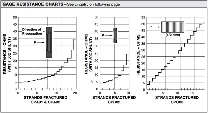
The Micro-Measurement Crack Propagation Gages (CPG) consist of multiple parallel resistor strands. These strands, when broken, indicate the rate of crack progression or propagation. When bonded to a structure, the progression of a surface crack through the gage pattern causes successive open-circuiting of the strands, resulting in an overall increase in total resistance. Please refer to the sensor datasheet for more information.
Measuring the Crack Propagation Gage resistance change
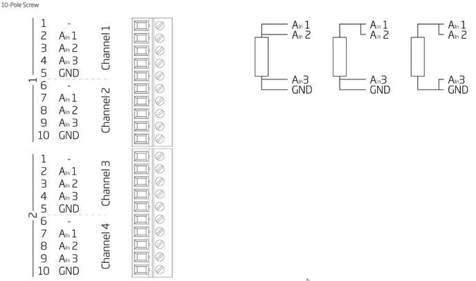
A CPG can be directly connected to the Q.series A105 using a 2-wire connection and an input range of 400 Ω. As only the relative change of resistance is crucial with a CPG, a 3- or 4-wire connection for accurate absolute resistance measurement is not required.
Taking the CPA-type gage as an example, the total resistance of a gage is around 120 Ohms, which falls within the input range of an A105 (400 Ω). If all 20 strands are undamaged, the gage provides a resistance of 5.224 Ω. If one strand is broken and 19 are intact, the resistance increases to 5.469 Ω, resulting in a resistance change of 0.245 Ω. Using a 400 Ω range, the A105 has an accuracy of 0.012 Ω, which is more than sufficient to detect this resistance change.
When using a 2-wire connection to the gage, it is necessary to jumper the open inputs on the module.