To measure RPM using an encoder, it is sufficient to measure the frequency of either channel A or B. If the direction of shaft rotation is not important, there is no need to configure the channel for counter or quadrature mode.
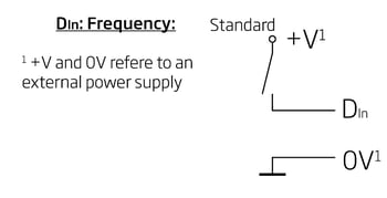
To measure RPM, connect either channel A or B of the encoder to a digital input (DIN) and configure the channel for standard frequency measurement.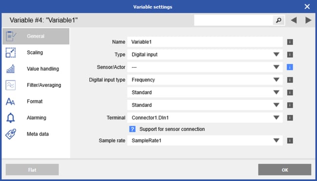
Once you have obtained a frequency measurement, you can convert it to RPM. For example, if you are using the Model 725 encoder with a maximum speed of 8000 RPM and 360 pulses per revolution:
- (8000 rev/min) x (1 min/60 sec) x (360 pulses/rev) = 48000 pulses/sec = 48 kHz
To scale the frequency to RPM in your measurement software:
-
Go to the Scaling section.
-
Manually enter "RPM" as the unit.
-
Define the scaling points as follows:
-
Point 1: 0 Hz = 0 RPM
-
Point 2: 48,000 Hz = 8000 RPM
-

Enter a suitable time base. For high-frequency signals, a short time base is sufficient to count enough signal edges (ramps). However, for low-frequency signals, a longer time base is required to capture enough transitions and ensure accurate measurement.

If you want to use the sensor as an encoder, you will only be measuring counts (pulses). To convert the counts to RPM, you need to compare the number of pulses measured within a known time interval.
The equation is:
- RPM = (Counts / Pulses per Revolution) × (60 / Time Interval [s])
For example, if you measure 720 pulses over 2 seconds, and your encoder has 360 pulses per revolution:
- RPM = (720 / 360) × (60 / 2) = 2 × 30 = 60 RPM