Driver Installation
- Download the LabVIEW driver file from the Gantner Instruments website
https://resources.gantner-instruments.com/download-labview-package - Unzip the LabVIEW folder, and copy and paste the entire Gantner Instruments folder into the following location: C:\Program Files\National Instruments\LabVIEW 201X*\instr.lib
*Depends on the version of LabVIEW installed - Inside the Gantner Instruments folder, you will find the 32 or 64-bit version of the giutility.dll. Copy and paste this file to the following location: C:\Windows\System32.
- Start the LabVIEW program. Create a blank VI.
- The Gantner VIs can be found in Instrument I/O > Instrument Drivers >
Gantner Instruments > Ethernet > Direct Ethernet Communications. - Inside the Gantner Instruments folder, the Driver Manual can be found. This manual describes the different VIs and examples of how to use them.
After installation, the GI DAQ Library pallet is integrated into the context menu (if installed using the zip file, the VIs will be found under Instruments IO > Instrument Drivers > Gantner Instruments).

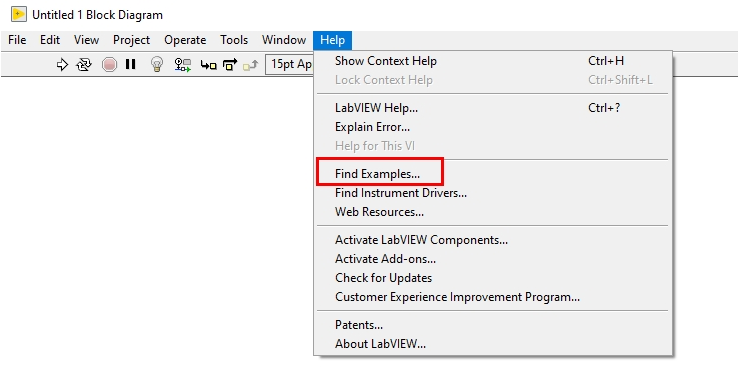
Examples
Some examples and tutorials can be found in the Help > Find Examples menu in LabVIEW.


They can also be found in the Ethernet folder in the zip file download
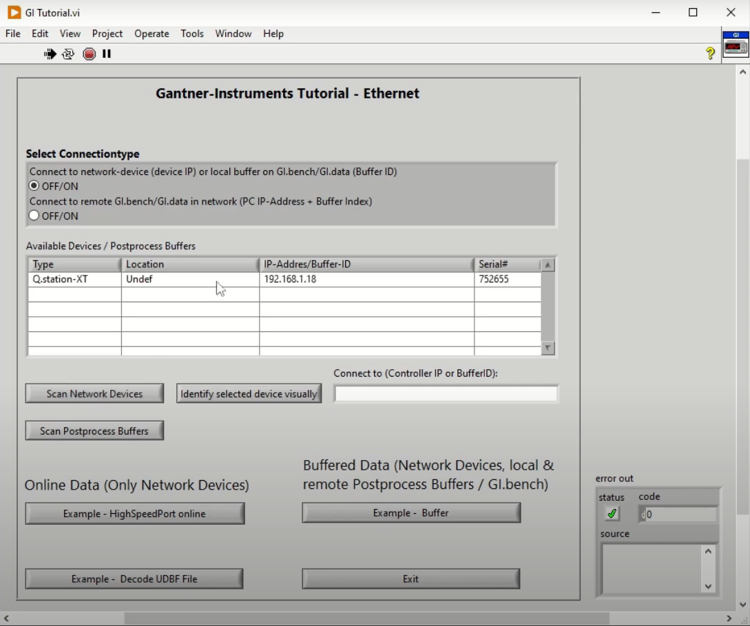
Ethernet Communication
The VIs enables data transfer over HighspeedPort TCP/IP protocol. The main VIs needed are the GI Initialize, GI Cleanup, and buffer or online communication
Types of Data
Online
Online communication allows for reading and writing Gantner data approx. 20-50 Hz (no data buffering). Use the GI Read or Write Online VI.
Using the channels' “ReadIndex” (= channel input index) or the “WriteIndex” (= channel output index) it is possible to read/write channel data. It is also possible to write to multiple output channels with an array (→ WriteCount).
All the necessary input/output access indexes of the channels, and other channel information (like Name, Type, data format, …), are available after the initialization of the connection.
Buffered
When using buffered communication data is read from a circular buffer on the Test Controller or from a local/remote PostProcess buffer, provided by GI.bench (GI.data). Buffered communication can not be used for writing values. Data is transferred in blocks, so it is possible the get all data with full sample rate (up to 100 kHz) out of the buffer.
To initialize a connection to a circular buffer on a Test Controller use the GI Highspeedport Buffer VI.
Depending on the data rate setting of the circular buffer it may be necessary to adjust some parameters to make sure that all data is transferred fast enough and to avoid a buffer overrun on the Q.station controller:
-
Buffer size in the controller (at least a few seconds of data should be buffered)
-
Cycle time of the function call in the LabVIEW application (between 20-50 Hz is recommended, the Q.station controller can do up to 100 Hz)
-
The number of max. frames to be read in one cycle (driver default = 5000). It may be necessary to increase this value for high sample rates in combination with the cycle time of the application to be sure that all frames can be read within one cycle. This parameter can be found within the “e.gate HighspeedPort Read Buffer.vi”
