Q.staxx module socket
Each Q.staxx module has a Harting 16-pole connector. Connections are done following the below pin assignment:
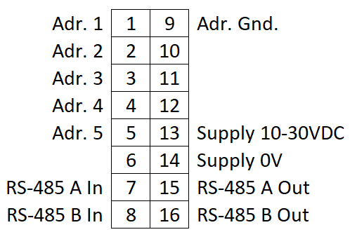
Communication
The modules communicate over the RS-485-based Localbus protocol. Comms going into the module are connected to pins 7 and 8 for RS-485 A/B IN. To connect comms to the next module, connect pins 15 and 16 on the first module to pins 7 and 8 respectively on the next module.
Example connection from Q.station to Q.staxx"
- UART 1
- A1 -> RS-485 A In
- B1 -> RS-485 B In
- UART 2
- A2 -> RS-485 A In
- B2 -> RS-485 B In
Power
A supply of 10-30 VDC is needed to power the modules. Power into the module is connected to pins 13 and 14 for supply and ground respectively. These can be used to run power to the next module as well.
Addressing
The address pins are for physically setting the module of the address (as opposed to in software).
- Address 1: bridge pin 1 and 9
- Address 2: bridge pins 2 and 9
- Address 3: bridge pins 1+2 to 9
- Address 4: bridge pins 3 and 9
- Address 5: bridge pins 1+3 to 9
- Address 6: bridge pins 2+3 to 9
Continue in the binary format as needed
Module connectors
The Q.staxx modules vary in connector depending on the module type.
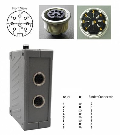
Q.staxx A101
Q.staxx A104

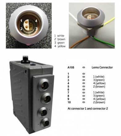
Q.staxx A105
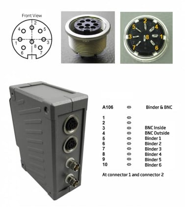
Q.staxx A106
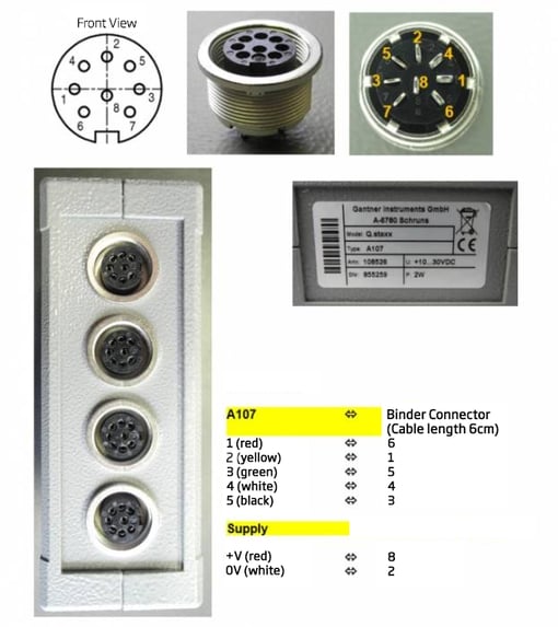
Q.staxx A107
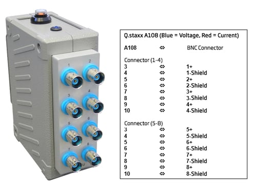
Q.staxx A108
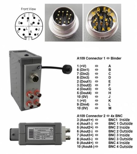
Q.staxx A109
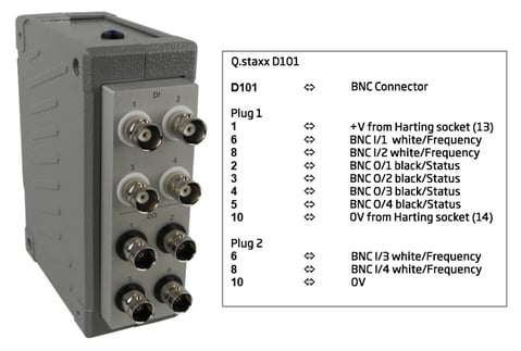
Q.staxx D101
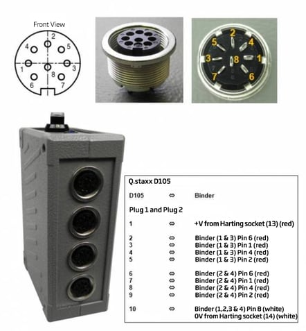
Q.staxx D104/D105
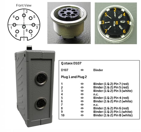
Q.staxx D107