
Setting up a quadrature encoder for bidirectional position or rotary frequency (RPM) measurement.
How does a quadrature encoder work?
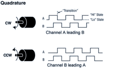
A quadrature encoder is an incremental sensor that produces square wave output signals. It has two output channels known as Signal A (or Channel A) and Signal B (or Channel B). These signals are phase-shifted by 90°, determining the direction of the encoder's movement.
In addition to direction, position can also be tracked using a quadrature encoder by generating an additional signal known as the Marker, Index, or Channel Z. This Z signal, generated once per complete revolution of the quadrature encoder, is frequently used to pinpoint a specific position during a 360° revolution.
RPM measurement
When you initiate measurement, both Channel A and Channel B will display the same frequency, with a 90-degree offset between them. Hence, using either A or B suffices for RPM measurement. The Z index can track total revolutions but is unnecessary for RPM calculation.
The encoder can be configured in two modes: frequency measurement or counter.
- Frequency Measurement: Employed for RPM measurement (use A or B).
- Counter: USed for measuring rotational angle and direction (employ A, B, and Z).
Thus, if RPM measurement is your sole requirement, you can measure the frequency of either A or B signal. If direction is inconsequential, there's no need to configure the channel as a counter/quadrature. For RPM measurement, configure the digital input as a standard frequency measurement.