Configuring thresholds for digital inputs
How to configure threshold values for digital inputs using A109, D101, D104, and D107 modules
Purpose
The digital input modules in the Q.series line of measurement modules can select the switching threshold. Signal voltage levels or TTL levels are the two threshold options.
The A109 module has one setting for all digital inputs
The D101/D104 modules allow you to select a threshold per each of the 2 connectors.
The D107 module has adjustable threshold settings in 256 steps (differential inputs: -20 VDC up to + 20 VDC, single-ended inputs: 0 VDC up to +26 VDC)
Threshold
- TTL logic:
- Signal voltage (0 / Low): <0.8 VDC
- Signal voltage (1 / High): >3 VDC
- HTL / 24 VDC logic:
- Signal voltage (0 / Low): -3 to 5 VDC (EN61131-2, Type 1)
- Signal voltage (1 / High): 11 to 30 VDC (EN61131-2, Type 1)
Specifications
- Maximum input voltage: 30 VDC
- Maximum input current: 2 mA
- Isolation voltage: 500 VDC
Setup with GI.bench
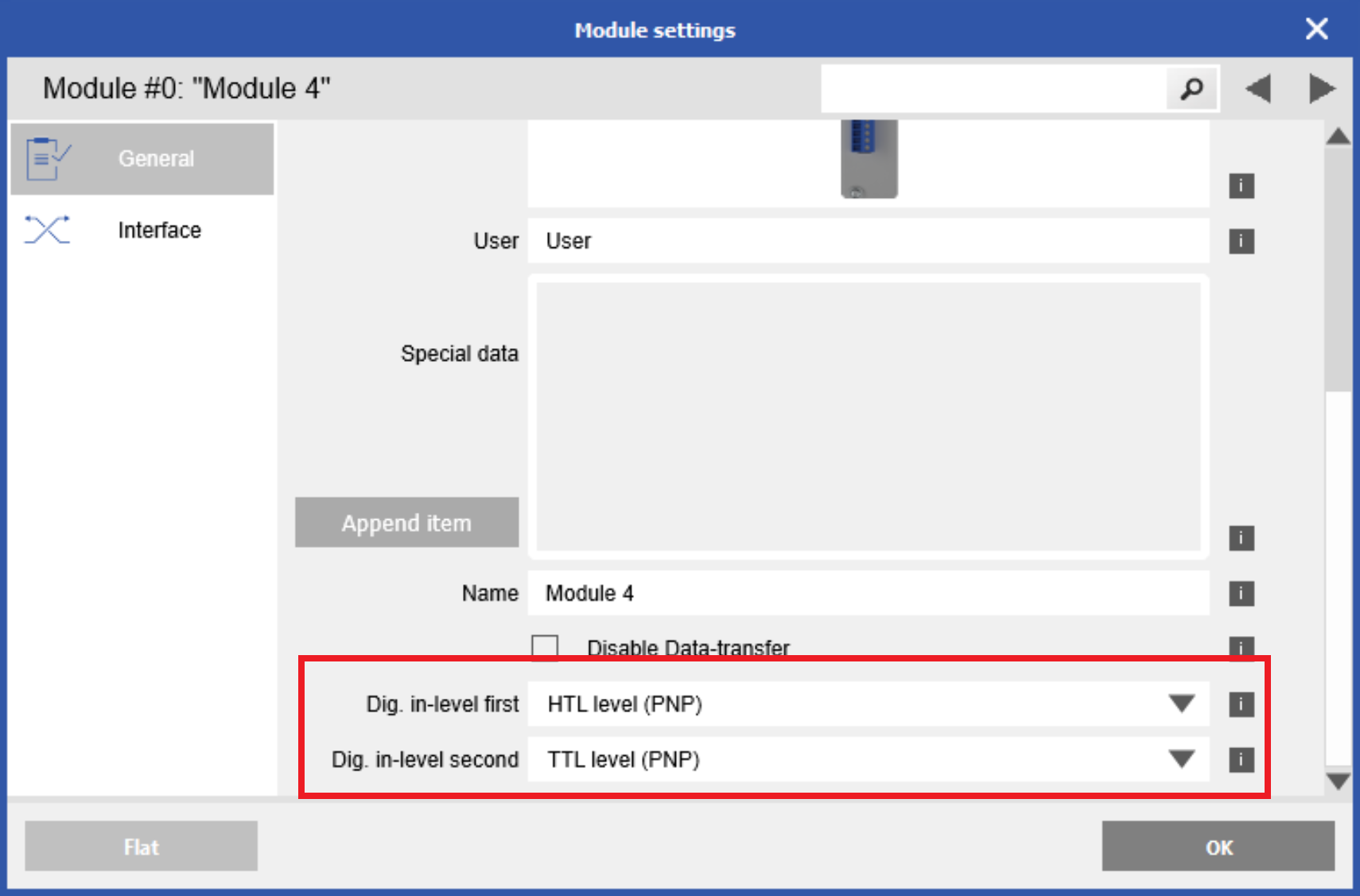
- Double-click on the module itself in the project window to open the module settings window.

- In the General section, navigate to the bottom for the threshold configuration parameters. The D101 / D104 will show a first and second threshold configuration parameter.

- Click OK, then write updates to the controller.
Setup with test.commander
- By default, the threshold is set to Signal Voltage.
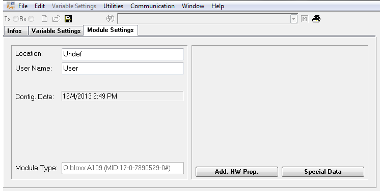
- Open the desired module in ICP100.
- Go to the Module Settings tab.

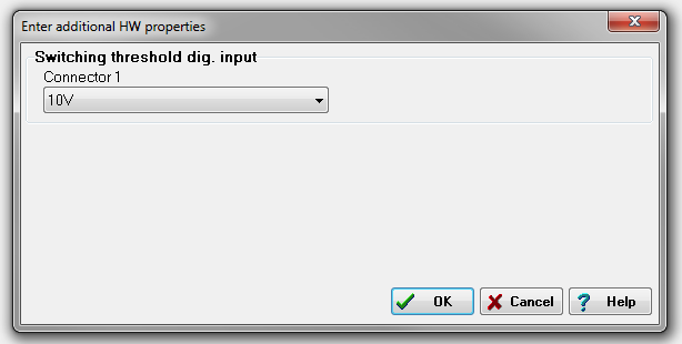
- Press the Add. HW Prop. Button and the following window will appear.

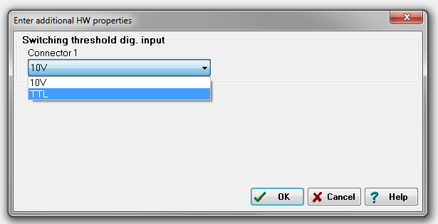
- Notice that Connector 1 (digital inputs on the A109 are assigned to Connector 1) has the
threshold configured for 10V (Signal Voltage option). - The threshold can be changed to TTL by selecting TTL. Click OK to confirm the change.

- Save the module configuration and update the project to the controller.