Description
https://dev.gantner-instruments.com/webfiles/public/Download/Software/DasyLab/Gantner-Instruments_DasyLab_V2.0.0.0.zip
user: support
pw: gins
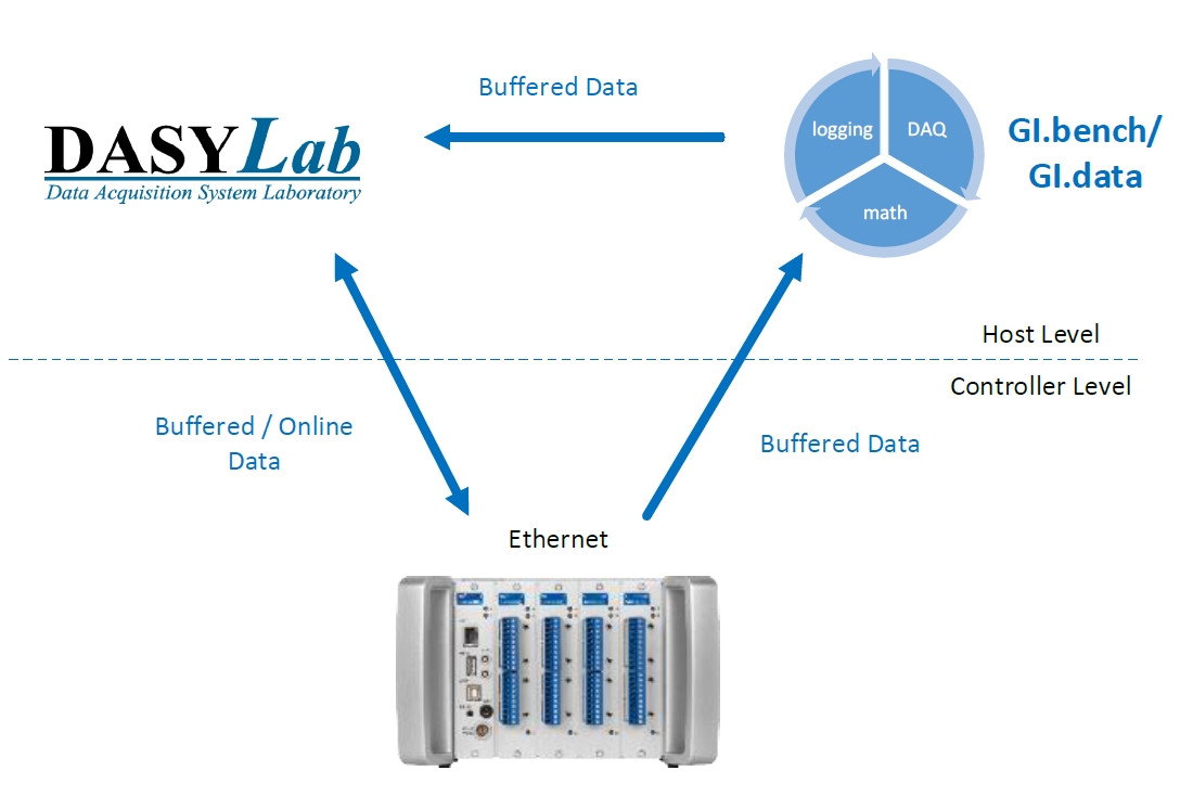
How to interface between DASYLab and Gantner Instruments hardware. The driver enables HighSpeedPort data communication between DasyLab and Gantner-Instruments e.- and Q.series Controllers, as well as data communication to local GI.bench (GI.data) buffers.
DasyLab, respectively the driver, is 32-bit. Use GI.bench in 32-bit for compatibility
Version: V2.0.0.0 (Dasylab 2016 v14), V1.0.0.8 (Dasylab V11/12/13)
The plugin uses Ethernet communications with a Gantner Instruments controller.
System Requirements
- giutility.dll (Highspeedport communication and device scan - this DLL is also installed with GI.bench)
- GInsDasyLab.dll (plugin)
- Ethernet Connection: Port 8001 TCP (if protocol needs to be forwarded or passed through any firewall)
- Port 5565 UDP (UDP Broadcast for module scan)
- DLLs at the install path or WINDOWS\system32
Overview
- Online (read + write): Each read/write channel configured in DASYLab causes a separate (!) communication on Ethernet! Therefore (depending on the number of configured channels) avoid high sample rates for “Online” communication (approx. 50 Hz DasyLab sample rate) due to performance reasons of the controller.
-
-
monitoring of slow changing values
-
slow control applications
-
control switches, relays,..
-
tare input channels
-
- Buffered (read only): On the controller it is possible to configure circle buffers (up to 4 on Q.station). Local data-buffers of GI.bench or other 3rd party software (using GInsData-API) can also be accessed in DasyLab. Circle buffers are filled with data frames exactly within the configured Synchronization Sample Rate (test.commander/GI.bench).
On direct buffer communication with a device, at each data request, the controller sends the complete buffer. The request rate between host PC and device is defined by the parameter “Comm.Delay (ms)” of the function-block. It is recommended to use slow rates (200 - 500 ms).
Recommended for:
-
monitoring of high dynamic valus
-
store data with an exact (FPGA controlled) sample distance
-
Installation
There are 2 steps required to attach this plugin to DASYLab:
- Copy DLLS
The plugin (dll) files need to be copied to the installation path of DASYLab:
- GInsDasyLab.dll
- GInsDasyLab.chm
- giutility.dll (32-bit)
- Register Plugin
The driver name needs to be added to the DASYLab.ini file
Windows 7 -> 10:
C:\Users\Public\Documents\DASYLab\14.0.1\ger\DASYLab.ini
In this .ini file there is a section [Extend], where the driver name has to be added:
[Extend]
DLL1=GInsDasyLab.dll
DLL2=DLAB_UX2.DLL #< not used
DLL3=DLAB_UX3.DLL
DLL4=DLAB_UX4.DLL
DLL5=DLAB_UX5.DLL
DLL6=DLAB_UX6.DLL
DLL7=DLAB_UX7.DLL
DLL8=DLAB_UX8.DLL
After storing DASYLab.ini, the driver will be loaded at the next start.
After installation, the Gantner-Instruments modules can be found at "Module -> I/O".
Also a new TimeBase is registered for the BufferReader module.
Configuration
With this plugin, changing any settings on the measurement system is impossible! It can only be used for Ethernet data communication. All configuration changes to the system must be done with GI.bench/test.commander. DASYLab can access the Ethernet data interface if the system configuration is done correctly.
Usage
The Gantner Instruments modules can be found at Module > I/O. Also, a new TimeBase is registered for the BufferedReader module.
IMPORTANT: Only buffered modules use this time base, only modules run with the DASYLab time base. The Sample Rate can not be modified because it is fixed to the system (synchronization sample rate). A detailed description of the plugin can be found in the module help section.
Function Blocks
3 function blocks are available:
-
Online Writer
-
Online Reader
-
Buffer Reader
Global Control
The “Global Control” settings of each function block are necessary to control the behaviour of the Ethernet communication of the driver.
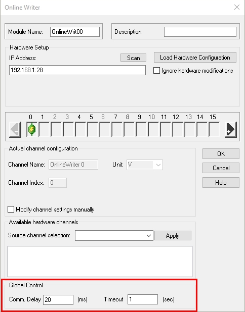
Comm. Delay
For Online Read/Write: this parameter has no function. Communication rate is defined by DasyLab sample rate.
For Buffer Communication: the communication delay defines how fast the driver calls data from the controller (not accurate).
Recommended values:
-
Buffer Reader: 200-500 ms
This parameter should be a compromise between fast data refresh and controller performance load!
If the delay is too big, values are “less online”, if it is too low, the performance of the controller could get worse!
The controller health should always be > 70 %. This can be checked via Online Device Status (GI.bench), Read Online State Info From Controller (test.commander, or with an additional virtual variable and the arithmetic function "GetSystemHealth()"
Timeout: The timeout defines the connection and communication timeout of the TCP/IP socket. This parameter should be increased, if a slow Ethernet/Internet connection is expected.