Driver
The most actual driver for Gantner Instruments Ethernet devices can be downloaded from the homepage in the following link: Gantner Instruments - Download Page (actual driver version: V2.0.0.0).
The driver was developed and tested with DASYLab Version 2016 (Version 14). A driver for previous DASYLab versions 11, 12, and 13 is also available (V1.0.0.8).
General Information
The driver enables HighSpeedPort data communication between DASYLab and the e.series, Q.series, and Q.series X controllers, as well as data communication to GI.bench (GI.data).
DASYLab and the DAYLab driver are 32-bit, therefore also use the 32-bit version of GI.bench.
System Requirements
-
DASYLab version >= 14
-
giutility.dll (Highspeedport communication and device scan, this DLL is installed with GI.bench)
-
GInsDasyLab.dll (DASYLab Plugin)
System Overview

HighSpeedPort TCP/IP
This is the Gantner Instruments-specific binary protocol for fast data transfer over Ethernet.
If the protocol needs to be forwarded or passed through any firewall, TCP Port 8001 has to be enabled.
The following types of data communication are possible:
-
Online (read + write): Each read/write channel configured in DASYLab causes a separate (!) communication on Ethernet! Therefore (depending on the number of configured channels) avoid high sample rates for “Online” communication (approx. 50 Hz DasyLab sample rate) due to performance reasons of the controller.
-
monitoring of slow changing values
-
slow control applications
-
control switches, relays, ...
-
tare input channels
-
…
-
-
Buffered (read-only): On the controller, it is possible to configure circle buffers (up to 4 on Q.station). Local data buffers of GI.bench or other 3rd party software (using GInsData API) can also be accessed in DasyLab. Circle buffers are filled with data frames exactly within the configured Synchronization Sample Rate (test.commander/GI.bench).
On direct buffer communication with a device, at each data request, the controller sends the complete buffer. The requested rate between the host PC and the device is defined by the parameter “Comm.Delay (ms)” of the function block. It is recommended to use slow rates (200 - 500 ms). Recommended for:-
monitoring of high dynamic values
-
store data with an exact (FPGA-controlled) sample distance
-
Configuration
The configuration of a Gantner Instruments system cannot be done with of DASYLab. The configuration software test.commander or GI.bench has to be used to change the system structure or modify the sample rate. Changing the DasyLab sample rate will not change the sample rate of the Gantner DAQ system.
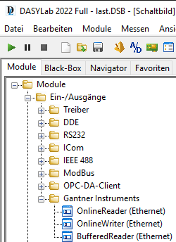
Function Blocks
3 function blocks are available:
-
Online Writer
-
Online Reader
-
Buffer Reader
Take care that the execution of the function blocks depends on the calls of DASYLab, which is a non-real-time application.
Global Control
The “Global Control” settings of each function block are necessary to control the behavior of the Ethernet communication of the driver.

Comm. Delay
For Online Read/Write: this parameter has no function. The communication rate is defined by the DASYLab sample rate.
For Buffer Communication: the communication delay defines how fast the driver calls data from the controller (not accurate).
Recommended values:
-
Buffer Reader: 200-500 ms
This parameter should be a compromise between fast data refresh and controller performance load!
If the delay is too big, values are “less online”, if it is too low, the performance of the controller could get worse!
The controller health should always be > 70 %. This can be checked via serial terminal (Q.gate/Q.pac) or with an additional virtual variable and the arithmetic function “SystemPerformance()”.
Timeout
The timeout defines the connection and communication timeout of the TCP/IP socket. This parameter should be increased if a slow Ethernet/Internet connection is expected.
Testing
To test a buffer communication and to ensure a smooth data transfer to avoid a buffer overrun (especially for high data rates), it is recommended to observe the actual buffer size of the controller during the data transfer. Therefore include the arithmetic function “BufferSize(<bufferindex>)” to your virtual variables of your controller:

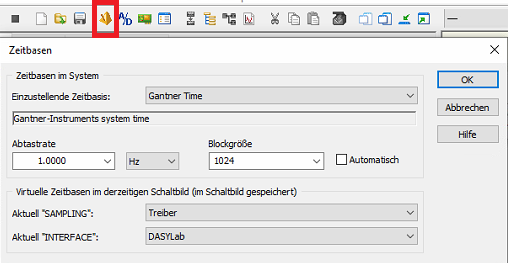
The parameter for “Blocksize” also needs to be set (→ see “Gantner Time” in timebase settings of DasyLab):
(info: “sample rate” setting in “Gantner Time” does not have any effect on the driver)

This parameter defines the transfer size between the Gantner driver and DASYLab. “1” means DASYLab picks up 1 data frame per cycle. This might be too slow for high data rates (sample rate of DASYLab < sample rate of the controller). This will cause the driver data buffer will be full → no new data can be transferred from the controller → buffer overrun in the controller.
This effect can be seen by observing the “BufferSize” variable of the controller (as mentioned above) in DASYLab. The value of this variable shows the fill state of the buffer in %.
Example:
-
buffer sample rate of the controller 5000 Hz
-
“Blocksize” set to “1”

So, the parameter for “Blocksize” should have a reasonable value, so that DasyLab can read all data from the driver and the buffer size will always be at for example < 2 %.
With the same example, we set the “Blocksize” to “500” → DasyLab transfers data blocks from the driver data buffer with 500 frames (correlates approx. 10 Hz rate between driver and DasyLab) → all data is transferred without any buffer overrun.

DASYLab 2022 example
Driver Installation
2 steps are necessary to attach the driver to DASYLab:
- Copy DLLs
The following files have to be copied to the installation path of DASYLab:
- GInsDasyLab.dll
- GInsDasyLab.chm
- giutility.dll (32-bit)
- Register Plugin
The driver name needs to be added to the DASYLab.ini file
Windows 7 -> 10:
C:\Users\Public\Documents\DASYLab\14.0.1\ger\DASYLab.ini
In this .ini file there is a section [Extend], where the driver name has to be added:
[Extend]
DLL1=GInsDasyLab.dll
DLL2=DLAB_UX2.DLL #< not used
DLL3=DLAB_UX3.DLL
DLL4=DLAB_UX4.DLL
DLL5=DLAB_UX5.DLL
DLL6=DLAB_UX6.DLL
DLL7=DLAB_UX7.DLL
DLL8=DLAB_UX8.DLL
After storing DASYLab.ini, the driver will be loaded at the next start.
After installation, the Gantner-Instruments modules can be found at "Module -> I/O".
Also, a new TimeBase is registered for the BufferReader module.
IMPORTANT:
Only buffered modules use this time base, online modules run with the DASYLab time base.
The SampleRate cannot be modified because it is fixed to the system sync. sample rate.
First Steps
build a basic project with a Buffered Read block from the Gantner IOs
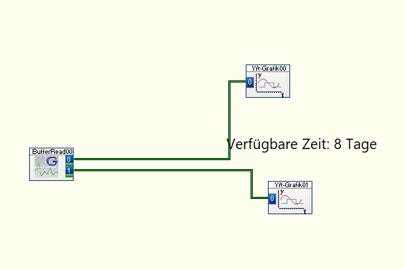
Check the timebases for the Block Size in Gantner Time
And the Samplerate in DASYLab

The Samplerate in Gantner Time is irrelevant. Data is requested with the Samplerate from DASYLab.
This results in "Gantner Block Size" * "DASYLab Samplerate" = acquirable sample rate
The acquirable sample rate should be at least a bit higher than the actual sample rate of your Gantner system. Otherwise, there will be data loss and non-equidistant data.
Known Issues
V2.0.0.0
-
Changing channel configuration (adding/removing channels via test.commander) → DASY-Lab project needs to be re-loaded (local process buffer must be reinitialized)
-
Online communication: each channel (read or write) causes a separate communication → it is recommended to use only “slow” rates < 50 Hz to avoid high load on the controller.
V1.0.0.8
-
The DasyLab driver cannot handle variable names with more than 19 characters. Take care of this in your test.commander configuration!
-
When adding/deleting channels in test.commander, the Gantner Instruments function blocks in your DASYLab project need to be updated. → Re-Load Hardware Configuration!
-
Drag and drop of display elements in DASYLab may cause DASYLab not to run smoothly (DASYLab is a none-real-time application) → this can lead to a problem with Online Read/Write function blocks, which are only executed when called by DasyLab (no buffered read/write → only 1 value at each call)
-
Writing on USINT16 or SINT16 variables does not work correctly (for example set value = 1 → channel value = 257) when using eGateHighSpeedPort.DLL V2.0.1.9., which is included in the driver setup. Using the newer version V2.0.2.1, this problem is solved.