Configuring the D101 to Read 8x Frequency Inputs using Special 8xChronos Firmware (test.commander)
Purpose
This article describes how to update the firmware version of a D101 module. The default firmware allows for up to 4 x frequency inputs. This special firmware allows a D101 to connect 8 x frequency inputs.
Items
- D101 module (Q.bloxx, Q.brixx, and Q.raxx)
- 8 x Frequency Input Firmware: 8xChronos
- test.commander or ICP-100 software
For setup where connection is directly to module instead of through controller, skip to step 16
Procedure
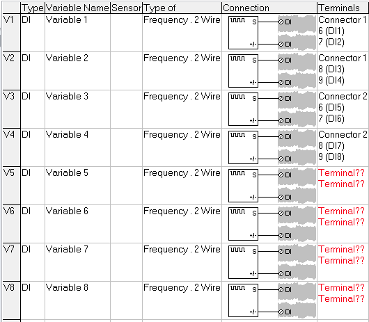
- The standard firmware version of the D101 module only allows up to 4 x frequency inputs (standard or 2-wire):
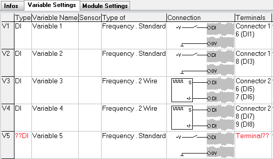
- The firmware of the D101 can be changed to accept up to 8 x frequency inputs.
- The firmware update process can be performed using test.commander (via Ethernet) or ICP100 (via Ethernet or Serial).
- The D101 must be attached to a controller if the update is performed via Ethernet. If performed via a serial connection, the D101 is connected to the PC via an RS485 to RS232 converter (i.e., ISK101, ISK103).
- Connect the D101 to a controller.
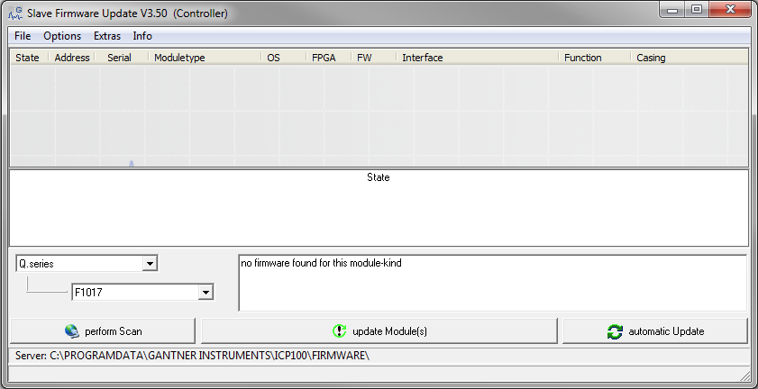
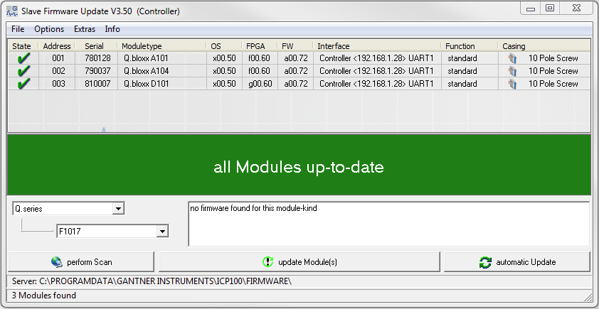
- Open test.commander. Utilities > Slave Firmware Update.
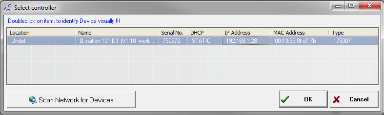
- Click on the Perform Scan button. The connected controller will be displayed; highlight the controller, and click OK.
- The software will compare the FW version inside the module to the FW version on the PC. If the FW version inside the module is older than available on the PC, a red X will be shown next to that module. If the FWversion inside the module is the same as the one available on the PC, a green check mark will be shown next to that module.
- Select the individual module to determine the different firmware available for that specific module. Selecting the D101, the FW types are shown.

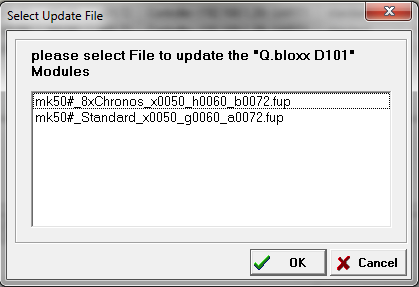
- Click the Update Module(s) button with the module selected. The software will ask to select the FW type to update. Select the 8xChronos file for the 8 x frequency input, and click OK.
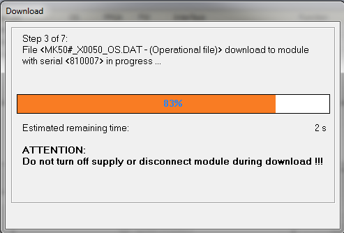
- The selected FW will now update to the module:
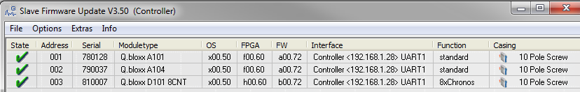
- After the update process is finished and the module restarts, the new FW is shown:
- Make sure to re-read the controller to update the configuration inside the controller.
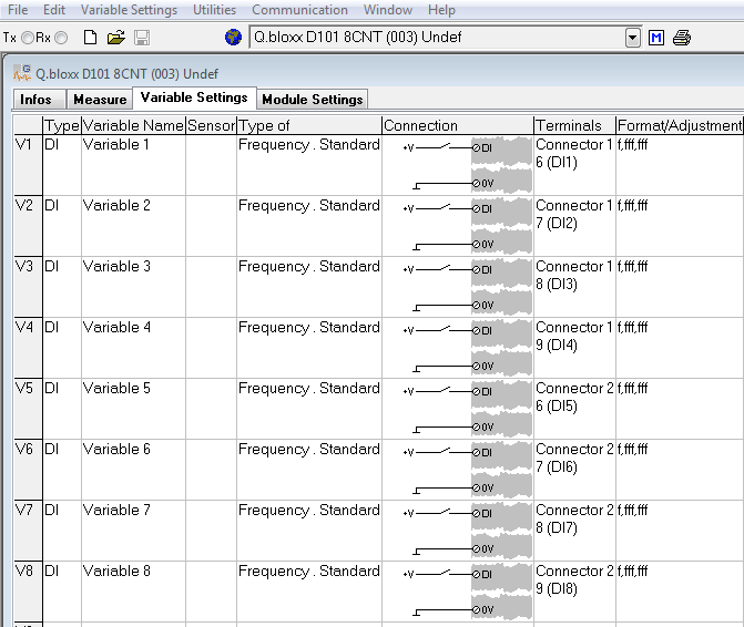
- After updating the new configuration type, the D101 will be displayed in the project window as a Q.bloxx D101 8CNT. With the new FW, having a maximum of 4 x 2-wire frequency inputs is still possible. But having up to 8 x standard frequency inputs is now possible.
With either the 4 x 2-wire or 8 x standard frequency inputs, it is possible to have up to 8 x digital outputs configuring as state, PWM, frequency, or process out.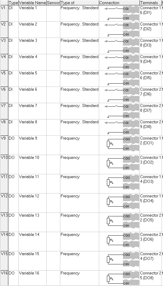
- Save the settings and update the project to the controller to apply all the changes.
- It is possible to perform the FW update using ICP100 only. Open ICP100, and select Communication > Parameters. The Communication window appears. If the D101 is connected to the PC using an RS485 to RS232 converter, choose RS232 Direct for the interface kind. If the D101 is connected via a controller, select TCP/IP Socket.
- Enter the static IP address of the controller and the port number, and click OK.
UART # Port # 1 8010 2 8011 3 8012 4 8013 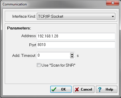
- Click on the Scan bus button in the toolbar of ICP100:
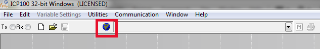
The attached modules will be displayed: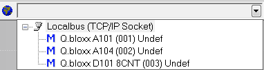
- The module can be selected in ICP100 and configured in the same manner as test.commander.