CAN FD configuration can be tricky and requires either a lot of know how or a tool to calculate the desired parameters.
Peak Systems provides a free Bitrate Calculation Tool:
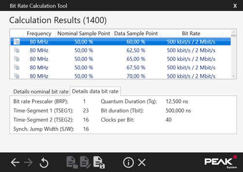
This tool allows the user to calculate working parameters for the CAN FD node easily
https://www.peak-system.com/Bit-Rate-Calculation-Tool.496.0.html?&L=1
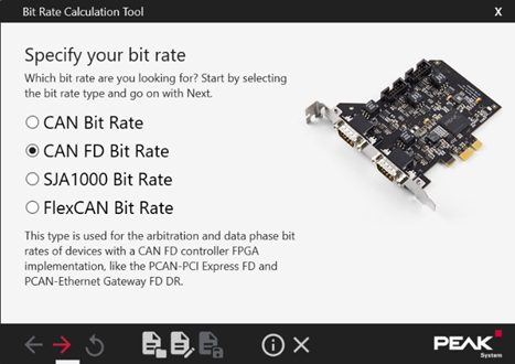
Going through the default settings of the calculation tool will provide several parameter sets, which should work for a CAN FD network.
Choose CAN FD to pull up the calculation for CAN FD parameters:
Set the desired Bitrates:
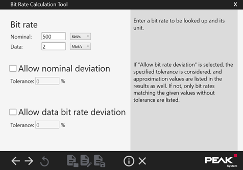
Set the internal calculation Frequency of the CAN FD Adapter:

For a first parameter set, leave everything on default:
CAN-FD
Using PEAK-System (PCAN-USB FD, PCAN-USB Pro FD), CAN-FD messages can also be sent and received with a Gantner Instruments controller (e.g. Q.station). For this purpose, the PCAN-Adapter must be configured with the following parameters according to the used CAN bus configuration. The theory behind these parameters is the time representation of a bit in CAN bus that consists of a synchonization (SYNC_SEG), propagation (PROP_SEG), phase buffer 1 (PHASE_SEG1) and phase buffer 2 (PHASE_SEG2) segment. Each of these segments is a multiple of time quanta and results in nominal bit time.
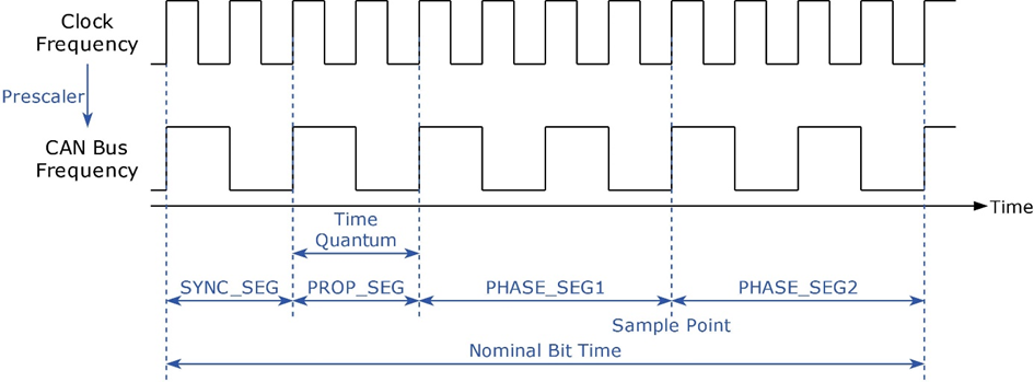
Clock Frequency = internal clock frequency of the USB CAN adapter
Prescaler in the example above is 2.
CAN Bus Frequency is not equal to CAN data rate, it is usually higher. Nominal Bit time is the time needed for one bit.
The graphic above shows the sample point of the Bit sits at around 66%. To replicate timings like the example the user then needs to check for a parameter set with the nominal sample point at or near 66%.
Clock Frequency:
The internal clock frequency of the PCAN adapter.
Baudrate Prescaler:
The prescaler converts the internal clock frequency of the adapter into the CAN bus frequency. The time quanta for bit representation result from this system frequency and must match other bus nodes.
Time Segment 1 and 2:
These parameters determine the length of PHASE_SEG1 and PHASE_SEG2 and thus set the sample point within the bit. The sample point must match other bus nodes.
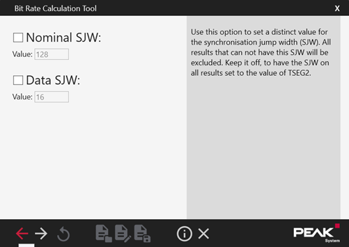
Sync. Jump Width:
Up to a certain degree, the adapter can resynchronize itself in order to compensate for an edge phase error. This parameter sets the limit for this resynchronization.
Due to higher data rates in comparison to normal CAN, the system can react sensitively to a wrong configuration, making communication between different nodes impossible. Since nominal and data rate can be different in CAN-FD, the parameters must be calculated and set for both rates.
