![favicon_GI.png]](https://knowledge.gantner-instruments.com/hs-fs/hubfs/favicon_GI.png?width=40&height=40&name=favicon_GI.png)
What Is a Strain Gauge Rosette and When Is It Used?
A strain gauge rosette combines multiple measuring grids at different angles to measure strain when the principal strain direction is unknown. Common configurations are 0°/45°/90° rectangular rosettes and 0°/60°/120° delta rosettes. Measurements in three directions enable engineers to calculate principal strains, their directions and, using material properties, the corresponding principal stresses.
What You Need for Strain Gauge Rosette Measurement with GI.bench
A strain gauge rosette measurement with GI.bench requires a suitable rosette with known gauge resistance, the correct bridge configuration and a compatible Gantner Instruments strain measurement module. Recommended modules include the Q.series X A116, A146 DB 120 or A146 DB 350. Accurate measurements require correct configuration of the gauge factor, bridge excitation and sensor parameters. GI.bench provides the DAQ environment for channel configuration, strain data acquisition and subsequent evaluation.
How Does a Strain Gauge Rosette Calculation Work?
A strain gauge rosette calculation uses three measured strain components to determine the principal strains ε₁ and ε₂ and their directions. Under plane stress conditions, the principal stresses can then be calculated from these strains using the material’s Young’s modulus and Poisson’s ratio, providing engineers with the magnitude and orientation of critical stresses at the measurement point.
How to Configure a Strain Gauge Rosette in GI.bench
Step 1: Connect the Strain Gauge Rosette to the DAQ Module
A three-element strain gauge rosette is electrically treated as three independent strain gauges. Each measuring grid is connected to a separate DAQ channel, typically designated A, B and C, and measured individually in a quarter-bridge configuration. Each active strain gauge forms one arm of a Wheatstone bridge, with the remaining bridge resistors provided by the DAQ module (or external bridge-completion circuitry).
Step 2: Configure the Strain Gauge Measurement Channels in GI.bench
The three measurement channels should use consistent settings for bridge excitation, bridge polarity, gauge (k-) factor and relevant sensor parameters.
-
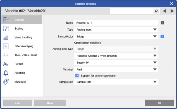
Open the settings of the relevant variable and, on the General tab, set Sensor to Bridge. Select the appropriate bridge sensor type and excitation voltage. Note that the available settings may vary depending on the measurement module used.
-
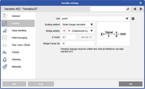
Next, open the Scaling tab and select the required engineering unit, typically µm/m. Set Scaling Method to Strain Gauge Calculator, then configure the Bridge Polarity (typically with tension defined as positive), the k-factor (gauge factor), and the Bridge Factor. For a quarter-bridge strain gauge circuit, set the Bridge Factor to 1.
-
Next, open the Scaling tab and select the required engineering unit, typically µm/m. Set Scaling Method to Strain Gauge Calculator, then configure the Bridge Polarity (typically with tension defined as positive), the k-factor (gauge factor), and the Bridge Factor. For a quarter-bridge strain gauge circuit, set the Bridge Factor to 1.
-
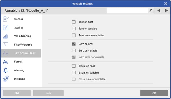
To enable zeroing of the strain gauge readings from the GI.bench user interface, select Zero on Host. For more information about the Zero and Tare functions, refer to this article: https://knowledge.gantner-instruments.com/zero-tare
Step 4: Create the Strain Gauge Rosette Calculation Outputs
Once the strain values εA, εB, and εC are acquired with the correct angular relationship between the strain gauge rosette grids, use the Rosette Calculation Wizard in GI.bench to calculate the principal strains, principal strain direction, and corresponding principal stresses.
-
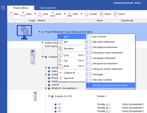
Right-click the Project and select Add > Add Strain Gauge Rosette Calculations. This opens the Rosette Calculation Wizard, which guides you through configuring the strain gauge rosette calculations.
-
In the Rosette Calculation Wizard, select the rosette configuration (Type) that corresponds to the physical arrangement of the strain gauge grids: 0°/90°, 0°/45°/90°, or 0°/60°/120°.
Next, assign the measurement channels to the strain gauge A, B, and C. The channel order must correspond exactly to the physical orientation of the individual gauge grids. The rosette calculation assumes that each input represents strain measured at a specific angle; therefore, assigning the channels in the wrong order will result in incorrect calculated values.
A strain gauge responds primarily to strain along its measuring-grid axis, but it also has a small sensitivity to strain perpendicular to this axis. The rosette calculation compensates for this effect using the transverse sensitivity coefficient. Enter Kt (%) as specified in the strain gauge manufacturer’s datasheet or calibration documentation for the particular gauge or rosette.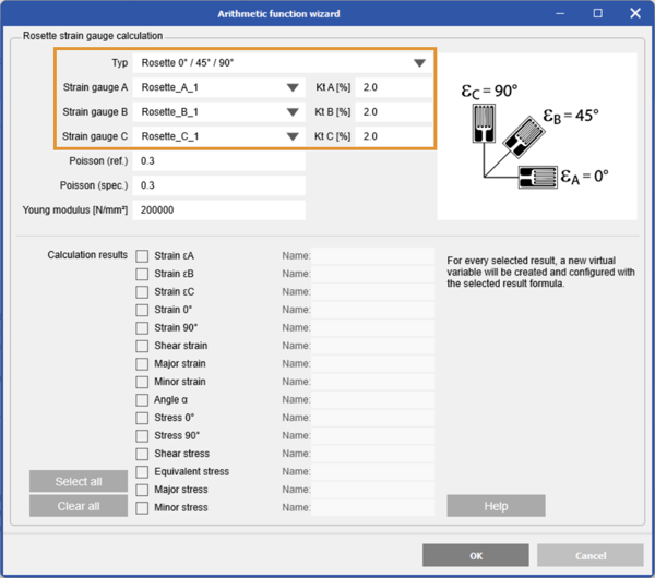
-
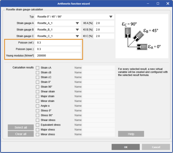
If stress is included in the required calculation outputs, enter the following material properties:
-
Poisson (ref.) - The Poisson’s ratio of the reference material used by the strain gauge manufacturer to determine or calibrate the specified gauge factor (k-factor). Because a real strain gauge has some transverse sensitivity, the specified gauge factor can depend slightly on the Poisson’s ratio of the reference specimen used during calibration. Use the value specified in the strain gauge manufacturer’s documentation.
-
Poisson (spec.) - The Poisson’s ratio ν of the specimen material on which the strain gauge rosette is installed. It describes the relationship between transverse and longitudinal strain under uniaxial loading.
-
Young’s Modulus - The Young’s modulus E of the specimen material, which describes its elastic stiffness and is required to convert the calculated strain into stress.
-
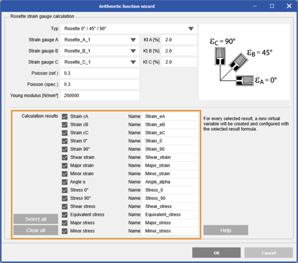
- Next, select the required calculation outputs. For each selected output, the wizard automatically creates a new virtual variable in the controller configuration. The available calculation outputs are explained in the table below.
|
Calculation |
Meaning |
|---|---|
|
Strain εA |
Direct strain measured by rosette grid B, normally oriented at 0°. |
|
Strain εB |
Direct strain measured by rosette grid B, normally oriented at 45°. |
|
Strain εC |
Direct strain measured by rosette grid C, normally oriented at 90°. |
|
Strain 0° |
Normal strain in the 0° or x-direction. For this rosette orientation, εx = εA. |
|
Strain 90° |
Normal strain perpendicular to the 0° direction. Here, εy = εC. |
|
Shear strain |
In-plane engineering shear strain derived from the three measurements: γxy = 2εB − εA − εC. |
|
Major strain |
Maximum principal strain at the measurement point. It is calculated from εx, εy and γxy and occurs along a direction where shear strain is zero. |
|
Minor strain |
Minimum principal strain, perpendicular to the major principal-strain direction. |
|
Angle α |
Orientation of the principal strain axes relative to the defined 0° reference direction. |
|
Stress 0° |
Normal stress in the 0° direction, calculated from the measured strains using Young's modulus E and Poisson's ratio ν, normally assuming plane stress. |
|
Stress 90° |
Normal stress in the 90° direction, calculated using the same material properties and plane-stress assumption. |
|
Shear stress |
In-plane shear stress calculated from shear strain using the material's shear modulus. |
|
Equivalent stress |
Scalar equivalent stress calculated from σx, σy and τxy. It is commonly used to compare a multiaxial stress state with the yield strength of a ductile material. |
|
Major stress |
Maximum principal stress calculated from σx, σy and τxy. |
|
Minor stress |
Minimum principal stress, acting perpendicular to the major principal-stress direction. |
How to Verify Your Strain Gauge Rosette Calculation
Verify a strain gauge rosette calculation by zeroing all measurement channels before loading and applying a known load case. Check each channel for the expected strain sign and magnitude, then confirm that the calculated principal strain direction is physically reasonable. Finally, compare measured strains and derived results with analytical calculations or FEA predictions.
Common Problems When Measuring Strain Gauge Rosettes
Accurate strain gauge rosette measurements depend on correct installation, wiring, configuration and material parameters. Common sources of error include:
-
Incorrect gauge orientation: The physical orientation of the strain gauge grids must match the angles assumed by the selected rosette configuration. Incorrect orientation or channel assignment can result in inaccurate principal strain values and directions.
-
Channels assigned in the wrong order: DAQ channels A, B and C must correspond to the correct physical grids. Swapped channels can significantly distort shear strain, principal strain and stress calculations.
-
Incorrect gauge factor: An incorrect gauge factor (k-factor) causes a proportional error in measured strain. Use the value specified for the installed strain gauge.
-
Wrong bridge configuration: Incorrect quarter-bridge configuration, bridge completion, polarity or excitation can cause scaling errors, reversed strain or excessive offsets.
-
Poor strain gauge bonding: Poor surface preparation, bonding or adhesive curing can prevent accurate strain transfer from the specimen to the gauge.
-
Offset or zero drift: Allow the system to stabilise and zero all strain channels before loading. Unexpected drift may indicate thermal, wiring or installation problems.
-
Incorrect Young's modulus or Poisson's ratio: Incorrect material properties lead to incorrect calculated stresses. Use Young's modulus and Poisson's ratio representative of the actual specimen material.
Frequently Asked Questions About Strain Gauge Rosettes
What Is a Strain Gauge Rosette?
A strain gauge rosette combines multiple strain gauge measuring grids at different angles at the same measurement point. A three-element rosette measures strain in three directions, enabling engineers to determine the maximum and minimum principal strains and their directions when the principal strain direction is not known in advance.
When Should I Use a Strain Gauge Rosette Instead of a Single Strain Gauge?
Use a strain gauge rosette when the strain state is biaxial or the principal strain direction is unknown. A single strain gauge measures strain only along one defined direction. A three-element rosette captures the in-plane strain state, allowing principal strains, shear strain and, with appropriate material properties, principal stresses to be calculated.
How Do You Calculate Principal Strain from a Strain Gauge Rosette?
For a 0°/45°/90° rectangular rosette, the measured strains εA, εB, and εC are used to calculate the maximum and minimum principal strains:
ε₁,₂ = (εA + εC) / 2 ± √[((εA − εC) / 2)² + (εB − (εA + εC) / 2)²]
where ε₁ is the maximum principal strain and ε₂ is the minimum principal strain. The same three measurements are also used to calculate the principal strain direction relative to the rosette reference axis.
What Is the Difference Between a 0°/45°/90° and 0°/60°/120° Strain Gauge Rosette?
Both configurations use three measuring grids to determine the in-plane strain state. A 0°/45°/90° rectangular rosette has grids separated by 45° and is widely used for experimental stress analysis. A 0°/60°/120° delta rosette uses three equally spaced directions. Both can determine principal strains and their orientation, but require different transformation equations.
How Do I Calculate Principal Stress from a Strain Gauge Rosette?
First calculate the principal strains from the three rosette measurements. For an isotropic material under plane-stress conditions, the corresponding principal stresses can then be calculated using the specimen’s Young’s modulus (E) and Poisson’s ratio (ν):
Maximum principal stress:
σ₁ = E / (1 − ν²) × (ε₁ + ν × ε₂)
Minimum principal stress:
σ₂ = E / (1 − ν²) × (ε₂ + ν × ε₁)
where E is Young’s modulus, ν is the specimen Poisson’s ratio, and ε₁ and ε₂ are the maximum and minimum principal strains, respectively.