![favicon_GI.png]](https://knowledge.gantner-instruments.com/hs-fs/hubfs/favicon_GI.png?width=40&height=40&name=favicon_GI.png)
To connect a Siemens SIMATIC STEP 7 PLC to a compatible Gantner DAQ module via PROFIBUS DP, install the Gantner GSD file in SIMATIC Manager, configure the PLC as the DP master, add the Gantner module as a DP slave, map its I/O data, compile the configuration, and download the project to the PLC.
Siemens SIMATIC STEP 7 and Gantner PROFIBUS DP Setup Overview
The Q.bloxx Classic and Q.series X modules can be supplied with specialized firmware to facilitate direct communication with the modules via Profibus DP. For further information on initiating communication with the Profibus DP modules, please refer to this article. The steps below describe how to set up communication with the Profibus DP modules using SIMATIC Manager.
Siemens STEP 7 and Gantner PROFIBUS DP Configuration Requirements
| Requirement | Configuration |
|---|---|
| PLC platform | Siemens SIMATIC |
| Engineering software | SIMATIC STEP 7 / SIMATIC Manager |
| Communication protocol | PROFIBUS DP |
| Siemens device role | DP Master |
| Gantner device role | DP Slave |
| Compatible Gantner families | Q.bloxx Classic / Q.series X with appropriate firmware |
| Device description | Gantner GSD file |
| Channel mapping | Match Gantner PROFIBUS representation/process image |
| Important limitation | Cyclic distribution of bus parameters must not be enabled |
Step 1: Create a SIMATIC STEP 7 Project and Add a SIMATIC 300 Station
-
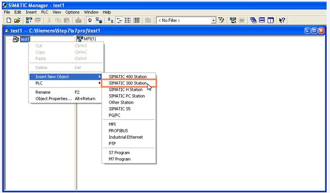
In SIMATIC Manager, initiate a new project and incorporate a SIMATIC 300 Station.
-
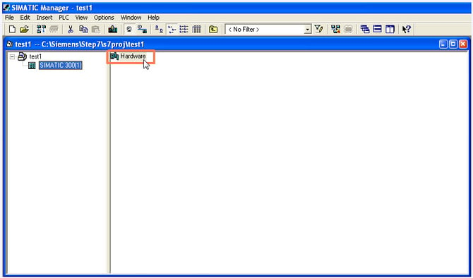
Navigate to the hardware configuration section in SIMATIC Manager.
Step 2: Install the Gantner PROFIBUS GSD File in SIMATIC Manager
-
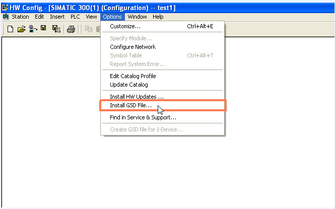
Double-click on the Hardware element in SIMATIC Manager to open the hardware configuration. Next, go to the Options menu and select Install GSD File... Ensure that both the "Slots and Components" and "Catalog" window are closed. After installing the GSD file, refresh the catalog.
The GSD files for modules are typically located in the ICP 100 program directory (C:\Users\Public\Documents\Gantner Instruments\ICP100\GSD), or they can be downloaded from the Gantner Instruments website: https://gi-productbase.gantner-instruments.com/en/rest_api/downloads/public/225/
Step 3: Configure the SIMATIC S7 PLC as the PROFIBUS DP Master
-
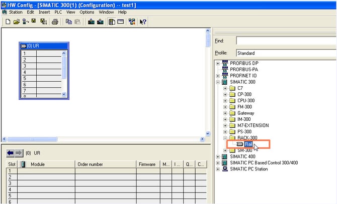
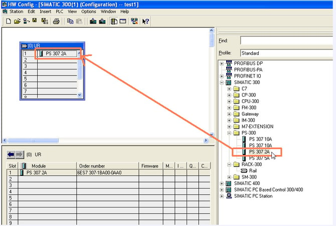
Upon installing the GSD files, the hardware configuration process must be initiated. Begin by attaching the PLC components to their respective slots with the correct type identifications. Drag and drop the profile rail from the right window into the upper left window to insert the profile rail element, which will then appear.
-
Drag and drop a Power Supply (PS) from the right window to the first channel of the profile rail element to add it.
-
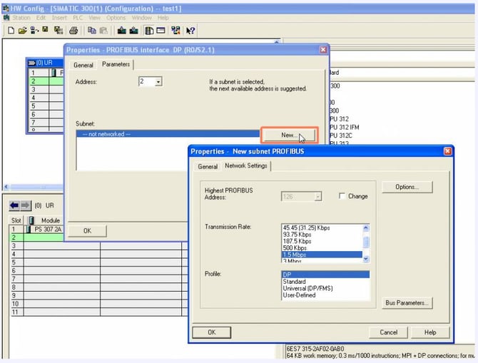
Drag and drop a PLC controller from the right window to the second channel of the profile rail element. This action will prompt the configuration window for the communication parameters of the DP master (PLC) to open. Clicking on the New button will lead you further to the bus configurations.
-
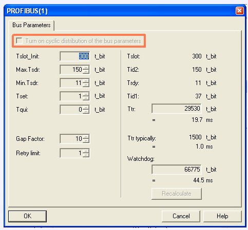
Navigate to the Network Settings tab to configure the general DP settings and the transmission rate. Click on the Bus parameters… button to access a new window for configuring the DP timing data settings. Do not activate the parameter "Turn on cyclic distribution of the bus parameters", as this is not supported by the modules.
Step 4: Add the Gantner Module as a PROFIBUS DP Slave
-
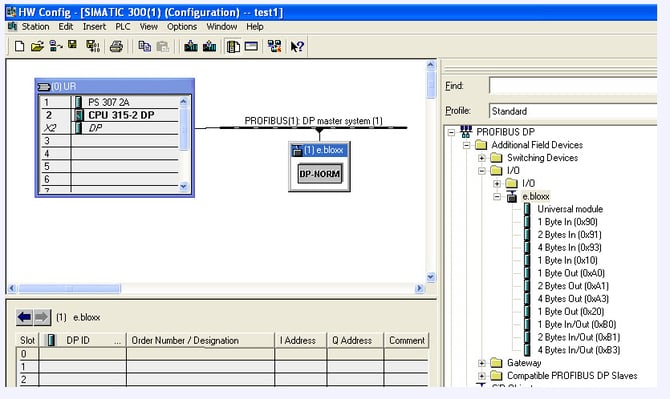
Drag and drop a Profibus DP module from the right window to the PROFIBUS-line in the left window to connect the slave to the bus line. Ensure to set the correct address of the module, noting that the address can be adjusted later if needed.
Step 5: Configure PROFIBUS DP Input, Output and Measurement Channels
-
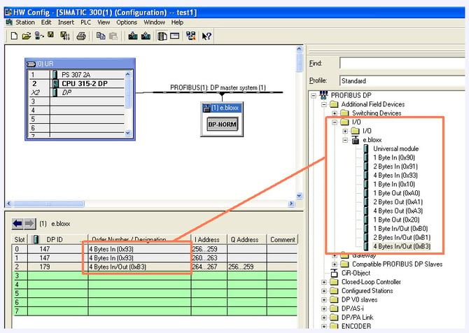
Slave setup can be accomplished through drag and drop functionality. In the right window, the required input and output data bytes are listed, which must be filled into the lower-left window based on the current slave configuration.
-
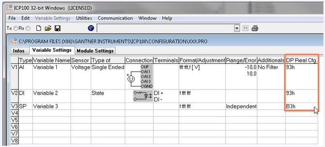
To set up the channels in Simatic, you must be familiar with the Profibus representation for each channel. This information can be obtained from the ICP 100 configuration.
-
Once all slaves are configured in the SIMATIC software as outlined above, navigate to the Station menu in Simatic and select Save and Compile.
-
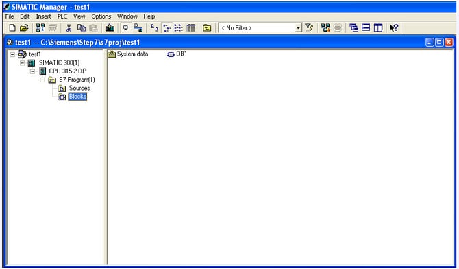
Switch to SIMATIC Manager, select Blocks, and load the project.
-
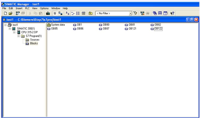
When duplicating an OP1 (organization block 1) at the block layer, additional OBs required for PLC communication with Profibus DP will be generated. Create OB80, OB81, OB82, OB85, OB86, OB87, OB121, and OB122. Detailed descriptions of organization blocks OB86 and OB122 can be found in Siemens Help.
Step 8: Download the SIMATIC STEP 7 Project to the PLC
-
By clicking the Download button, the entire SIMATIC project will be transferred to the PLC.
Frequently Asked Questions About SIMATIC STEP 7 and Gantner PROFIBUS DP
How do I connect a Gantner DAQ module to a Siemens SIMATIC STEP 7 PLC?
Install the appropriate Gantner GSD file in SIMATIC Manager, configure the Siemens PLC as the PROFIBUS DP master, add the Gantner module as a PROFIBUS DP slave, assign its address and I/O data, compile the configuration, and download it to the PLC.
Where can I find the GSD file for Gantner PROFIBUS DP modules?
The article identifies the ICP 100 GSD directory as C:\Users\Public\Documents\Gantner Instruments\ICP100\GSD and also links to a Gantner download resource.
Which Gantner modules can communicate with SIMATIC STEP 7 over PROFIBUS DP?
The guide states that Q.bloxx Classic and Q.series X modules can be supplied with specialized firmware for direct PROFIBUS DP communication. Check the specific module and firmware before configuration.
Which organization blocks are required for PROFIBUS DP communication?
The existing procedure instructs users to create OB80, OB81, OB82, OB85, OB86, OB87, OB121 and OB122, with Siemens Help referenced for further information about OB86 and OB122.
What PROFIBUS setting should not be enabled with Gantner modules?
When configuring DP timing data, do not enable “Turn on cyclic distribution of the bus parameters”, because the guide states that this option is not supported by the modules.