Procedure
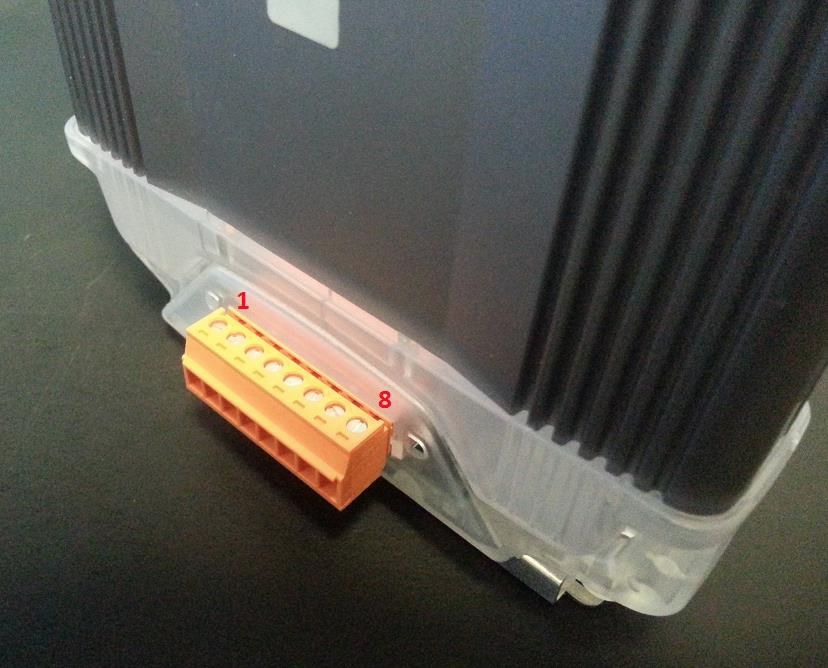
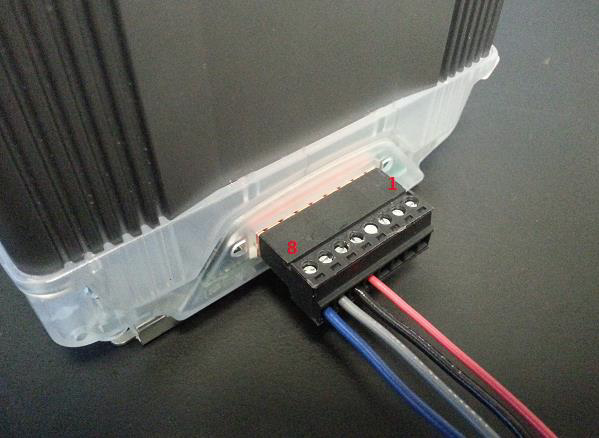
- Using 1 x Q.bloxx-CONL8O (qty. 1 is included with each Q.station or Q.gate; others must be purchased separately) Power and comms can be connected to the bottom of a Q.station 101, or left side of a Q.station with an extension socket, Q.gate, or Q.bloxx module.
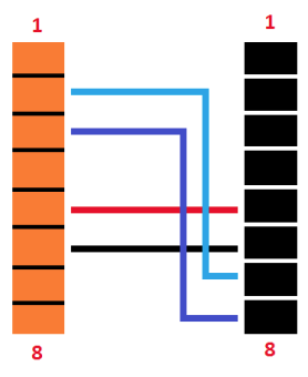
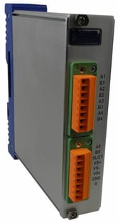
 PIN CONNECTION
1 Sync A
2 UART 2B
3 UART 2A
4 Sync B
5 +10 to 30 VDC
6 0V
7 UART 1B
8 UART 1A
2. Using 1 x Q.bloxx-CONR8B (purchased separately) connected to the right side of a Q.gate or Q.bloxx module, power, and comms can be connected or extended to another module.
PIN CONNECTION
1 Sync A
2 UART 2B
3 UART 2A
4 Sync B
5 +10 to 30 VDC
6 0V
7 UART 1B
8 UART 1A
1 Sync A
2 UART 2B
3 UART 2A
4 Sync B
5 +10 to 30 VDC
6 0V
7 UART 1B
8 UART 1A
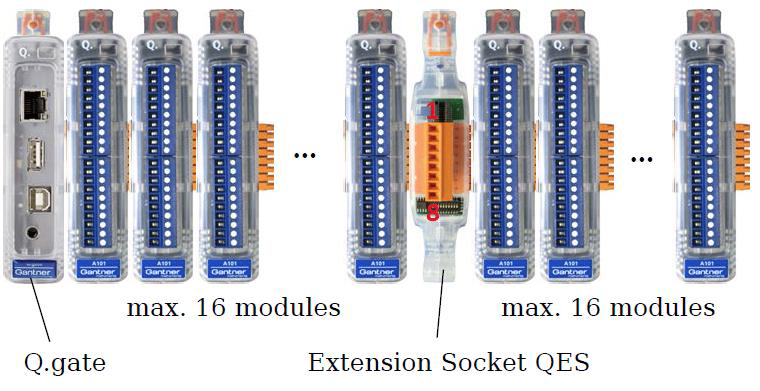
Connecting Q.bloxx Modules to a Q.station X:
An extension socket or UART/power device is needed to provide wiring connections from the Q.station X to the Q.bloxx-CONL8O for the Q.bloxx module. The function of the socket and UART/power is identical, one just has the full metal housing with connectors brought to the front.
Connect from the desired UART (e.g. UART 1: A1/B1) to 1A/1B on the Q.bloxx-CONL8O attached to the Q.bloxx module)
Connecting Q.bloxx Modules to UART2 of a Q.gate:
Option 1:
A Q.bloxx-QES (Q.bloxx Extension Socket) can be used if the modules are all connected.
- Supply power to the QES
- PIN 5: +10 to 30 VDC (each module requires approx. 2W)
- PIN 6: 0V
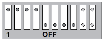
- Set the DIP switches on the QES
- DIP switches 1, 2, 3, and 4 are ON, and DIP switches 5, 6, 7, and 8 are OFF
Option 2:
If the modules are distributed in multiple locations, Q.bloxx-CONL8O and Q.bloxx-CONR8B can be used.