![favicon_GI.png]](https://knowledge.gantner-instruments.com/hs-fs/hubfs/favicon_GI.png?width=40&height=40&name=favicon_GI.png)
Gantner Instruments Q.bloxx Classic and Q.series X modules require dedicated firmware for direct PROFIBUS DP communication. Configuration involves connecting the module, installing the appropriate General Station Description (GSD) file in the PROFIBUS master and mapping the measurement data. Pay particular attention to the RS485 wiring: the A/B terminal designations differ between the module and PROFIBUS master.
In order to communicate directly with PROFIBUS DP to the Q.bloxx Classic or Q.series X modules, the modules need to be supplied with dedicated firmware. Please contact your local Gantner Instruments representative for further assistance.
PROFIBUS DP Technical Documentation
Configuring Gantner Modules for PROFIBUS DP
In order to link the PROFIBUS DP modules to a PC, a USB-to-RS485 converter is necessary.
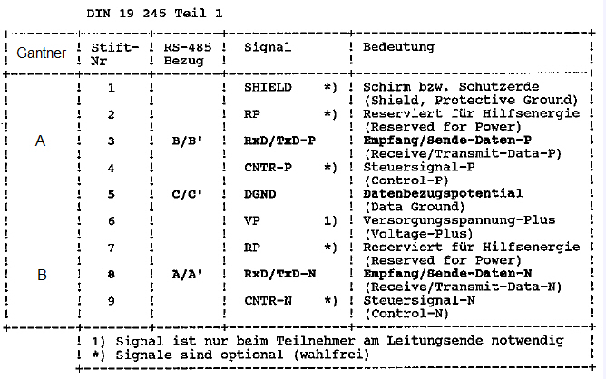
PROFIBUS DP Wiring and RS485 Pin Assignment
IMPORTANT: The A and B pins of the RS-485 interface on Q.bloxx Classic and Q.series X modules do not correspond directly to the PROFIBUS A and B signal lines. Do not assume that identically labelled terminals have the same signal assignment.
Connect the interfaces as follows:
- PROFIBUS master terminal A → Gantner module terminal B
- PROFIBUS master terminal B → Gantner module terminal A
Refer to the wiring diagram below and verify the terminal assignment before establishing communication.
Downloading and Installing Gantner PROFIBUS GSD Files
GSD files contain essential information about a module's capabilities, including supported communication parameters and available diagnostic functions. They enable system integrators to configure and integrate modules into a PROFIBUS network. GSD files follow a standardised format defined by the PROFIBUS specification.
The GSD files for Gantner Instruments modules are typically available in the ICP 100 installation directory: C:\Users\Public\Documents\Gantner Instruments\ICP100\GSD
Alternatively, they can be downloaded from the Gantner Instruments website:
https://gi-productbase.gantner-instruments.com/en/rest_api/downloads/public/225/
Reading PROFIBUS DP Diagnostic Data
Diagnostic data must be requested by the PROFIBUS master. Using the GSD file, the master can interpret the diagnostic information and identify status or error messages. The diagnostic data consists of 8 bytes, structured as follows:
|
byte 1 |
byte 2 |
byte 3 |
byte 4 |
byte 5 |
byte 6 |
byte 7 |
byte 8 |
|---|---|---|---|---|---|---|---|
|
framesize |
7..0 |
15..8 |
23..16 |
31..24 |
39..32 |
47..40 |
55..48 |
Unit_Diag_Bit(16) = "Underrange Input 1"
Unit_Diag_Bit(17) = "Overrange Input 1"
Unit_Diag_Bit(18) = "Underrange Input 2"
Unit_Diag_Bit(19) = "Overrange Input 2"
Unit_Diag_Bit(20) = "Underrange Input 3"
Unit_Diag_Bit(21) = "Overrange Input 3"
Unit_Diag_Bit(22) = "Underrange Input 4"
Unit_Diag_Bit(23) = "Overrange Input 4"
Unit_Diag_Bit(24) = "Underrange Input 5"
Unit_Diag_Bit(25) = "Overrange Input 5"
Unit_Diag_Bit(26) = "Underrange Input 6"
Unit_Diag_Bit(27) = "Overrange Input 6"
Unit_Diag_Bit(28) = "Underrange Input 7"
Unit_Diag_Bit(29) = "Overrange Input 7"
Unit_Diag_Bit(30) = "Underrange Input 8"
Unit_Diag_Bit(31) = "Overrange Input 8"
Unit_Diag_Bit(32) = "Underrange Output 1"
Unit_Diag_Bit(33) = "Overrange Output 1"
Unit_Diag_Bit(34) = "Underrange Output 2"
Unit_Diag_Bit(35) = "Overrange Output 2"
Unit_Diag_Bit(36) = "Underrange Output 3"
Unit_Diag_Bit(37) = "Overrange Output 3"
Unit_Diag_Bit(38) = "Underrange Output 4"
Unit_Diag_Bit(39) = "Overrange Output 4"
Unit_Diag_Bit(48) = "socket failure"
Unit_Diag_Bit(49) = "Addr from dipp switch"
Unit_Diag_Bit(50) = "Config from Socket"
Unit_Diag_Bit(52) = "not used with Profibus"