![favicon_GI.png]](https://knowledge.gantner-instruments.com/hs-fs/hubfs/favicon_GI.png?width=40&height=40&name=favicon_GI.png)
The GInsPhotonFirstPlugin integrates PhotonFirst GTR and SGTR Fiber Bragg Grating (FBG) interrogators with Gantner Q.station 101 and Q.station X controllers. It maps fiber-optic sensor measurements into Q.station data streams and process-image variables, enabling synchronized acquisition, monitoring, unit conversion, fieldbus integration, and analysis alongside electrical sensor data.
PhotonFirst FBG Interrogator Integration Overview
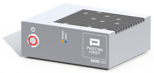
PhotonFirst measures physical parameters by transmitting light through an optical fiber and analyzing the reflected signals from FBG sensor elements. Differences between the emitted and reflected light are processed, via a photonic integrated circuit (PIC), into measurement values such as temperature, strain, pressure, or shape.
The plugin currently supports two PhotonFirst FBG interrogators:
- GTR FBG Interrogator - A single-channel device delivering 1 pm precision and high-speed sampling in a compact, ready-to-use platform.
- SGTR Multichannel FBG Interrogator - An eight-channel system offering fast multiplexing, high resolution, and high sampling rates per channel in a compact SWaP-optimized design.
System Requirements for the GInsPhotonFirstPlugin
The minimum system requirements for this plugin are:
- Q.station 101 / Q.station X
-
Q.station firmware V2.18.0
How to Install the PhotonFirst FBG Interrogator Plugin
- Download the correct plugin version that matches the controller firmware version from the Gantner public download area.
- For installation instructions please refer to the page: installing a plugin.
How to Configure the PhotonFirst FBG Interrogator Plugin
In general, the plugin maps the data received from the interrogator to an additional data stream on the Q.station controller. Configuration of the plugin is performed via a dedicated web interface.
In fiber-optic sensing systems, a channel refers to an interrogator input used to connect a fiber-optic cable. A sensor refers to an individual FBG sensing element embedded within that cable. Consequently, a single channel can host multiple sensors along the same fiber.
-
On the controller create an Additional datastream.
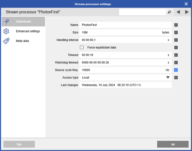
-
The following interrogator variables can be included in the data stream. When the variable names follow the naming convention below, the plugin automatically maps them to the data stream when you click Save in the web interface.
-
SensVal-XY: Sensor value, where X = channel number 1–8,
Y = sensor number 1–8. -
SensCnt-X: Number of sensors detected in channel X 1–8.
-
SensState-X: Sensor state in channel X 1–8.
-
MsgTime: Timestamp of the message.
-
MsgCnt: Message counter.
-
MsgSwState: Current position of the SGTR multiplexer 0–7.
-
-
[Optional] If the interrogator variables are needed for applications beyond data logging and monitoring - such as conversion to fieldbus protocols (EtherCAT, ProfiNET, CAN) or use in dashboard SingleStat elements (numeric displays, gauges, LEDs) - they must also be mapped to the controller’s virtual variables (process image) using the same naming convention.
-
Open the plugin web interface via the Project State view in Cockpit (GI.bench v1.18.0 or later) or web browser and enter http://[ipaddress]:8090/GInsPhotonFirstPlugin, where [ipaddress] represents the IP address of the controller.
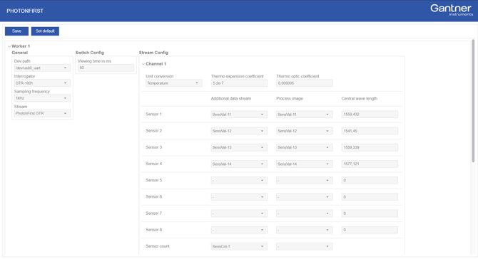
Configure the PhotonFirst GTR or SGTR Connection
Plugin Configuration Commands
-
Save: Saves all settings.
-
Set default: Resets the complete plugin to its default settings, deleting all settings.
Step 1: Configure the Interrogator and Sampling Settings
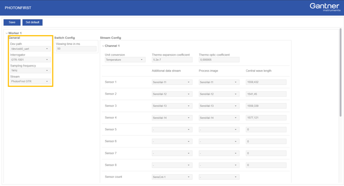
-
Dev path: The USB port on the controller to which the interrogator is connected.
-
Interrogator: Select the interrogator model, either the GTR single-channel interrogator (GTR-1001) or the SGTR multichannel interrogator (SGTR-1001).
-
Sampling frequency: The sampling rate configured for the interrogator.
-
Stream: The additional data stream on the controller where the data will be written.
Ensure that the source cycle frequency of the additional stream, the interrogator sample rate, and the plugin settings are all configured to the same sampling rate.
Step 2: Configure SGTR Channel Switching
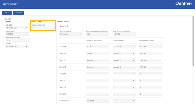
-
Start channel: First active channel to read from the multiplexer [0-7].
-
End channel: Last active channel to read from the multiplexer [0-7].
-
Viewing time (ms): Duration spent reading each channel before switching to the next. The default is 50 ms.
Step 3: Map FBG Sensor Data and Convert Wavelength, Strain, and Temperature
In the Stream Config section, the individual channel(s) and sensor mappings to the data stream and process image (via virtual variables) can be configured.
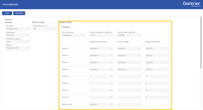
-
Unit conversion:
-
CoG [Center of Gravity]: The absolute, calibrated central wavelength value.
-
Wavelength [nm]: The CoG value converted to actual wavelength value.
-
Microstrain [µε]: The CoG value converted to microstrain.
-
Strain coefficient: The strain-optic coefficient describes how mechanical strain changes the optical fibre’s refractive index (approximately 0.22 for silica).
-
-
Temperature [°C]: The CoG value converted to temperature.
-
-
-
-
Thermo expansion coefficient: The coefficient of thermal expansion (approximately 5.2 × 10⁻⁷ K⁻¹ for silica) used to convert the measured wavelength shift into a temperature value for this channel.
-
Thermo optic coefficient: The thermo-optic coefficient (approximately 5–10 × 10⁻⁶ °C⁻¹ for silica) used to convert the measured wavelength shift into a temperature value for this channel.
-
-
-
Additional data stream: Select the stream variables to which the sensor data should be mapped. If the default naming convention is used, the mapping will be done automatically.
-
Process image: Select the virtual variable (also known as process image variables) to which the sensor data should be mapped. If the default naming convention is used, the mapping will be done automatically.
-
Central wave length: The known central wavelength of the sensor (λ₀), required for offset compensation for strain and temperature measurements.
Frequently Asked Questions About PhotonFirst FBG Interrogator Integration
Which PhotonFirst FBG interrogators are supported by Gantner DAQ system?
The GInsPhotonFirstPlugin supports the PhotonFirst GTR-1001 single-channel FBG interrogator and SGTR-1001 multichannel FBG interrogator. The SGTR provides eight channels for multiplexed fiber-optic sensor measurements.
Which Gantner controllers support the GInsPhotonFirstPlugin?
The plugin supports Gantner Q.station 101 and Q.station X controllers. Q.station firmware version 2.18.0 or later is required.
Can PhotonFirst FBG measurements be combined with electrical sensor measurements?
Yes. The plugin maps PhotonFirst FBG measurements into Q.station data streams, allowing fiber-optic measurements to be acquired and analyzed within the same Gantner data acquisition system as electrical sensor measurements.
Can FBG measurements be converted to strain and temperature?
Yes. The plugin supports the FBG center-of-gravity (CoG) value, wavelength in nanometers, microstrain (µε), and temperature in °C. Strain and temperature conversion can be configured using the sensor's central wavelength and appropriate strain-optic, thermal expansion, and thermo-optic coefficients.
Can PhotonFirst FBG data be used with EtherCAT, PROFINET or CAN?
Yes. FBG measurement variables can be mapped to Q.station virtual variables in the process image for applications beyond data logging, including fieldbus communication such as EtherCAT, PROFINET and CAN, as well as dashboard visualization.