![favicon_GI.png]](https://knowledge.gantner-instruments.com/hs-fs/hubfs/favicon_GI.png?width=40&height=40&name=favicon_GI.png)
Setting the UART interface
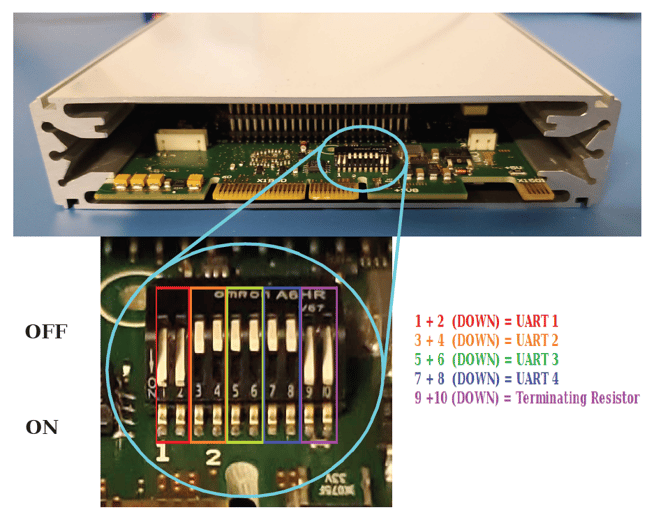
The RS-485 slave interface (UARTs 1 through 4) and the terminating resistor are configured using the DIP switch located inside the Q.series XL module, directly on the CPU board. UARTs are assigned using position pairs 1+2, 3+4, 5+6, and 7+8 (red, orange, green, and blue). Positions 9+10 (purple) activate the terminating resistor used to terminate the UART.
The last module of each UART interface must be terminated with a resistor. If a UART is not terminated, reflections may occur on the bus, leading to disturbances or even loss of data transmission.
Setting the module's address
Module addresses can be defined using the DIP switches on the socket. DIP switch positions 1 through 7 are used to assign module addresses in binary form. Address 0 indicates no fixed hardware configuration. In this case, the address can be set using the Setup Assistant.
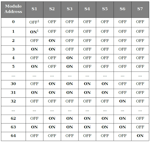
When configuring module addresses, start with address "1" on each UART and assign sequential numbers without leaving gaps.
Location of the address DIP switches on the Q.series X socket:
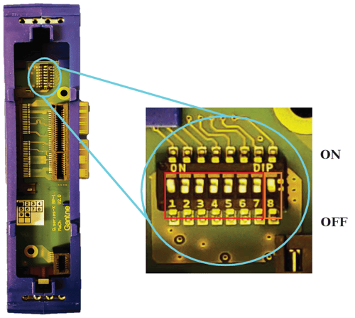
Location of address DIP switches on Q.series Classic socket:

The 8th switch activates the hot swap feature. When enabled, this stores the module configuration in the socket, allowing for the replacement of faulty modules with others of the same type.
Setting the module's address with GI.bench
- Run GI.bench
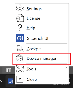
- Right-click GI icon in PC taskbar > Device Manager
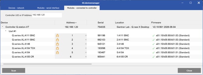
- Go to the Modules - connected to controller tab, enter controller IP address, click Scan
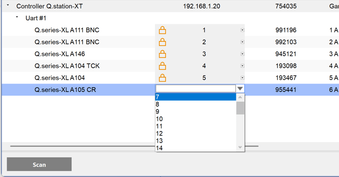
- Click the drop-down arrow next to the address to select the new address for that specific module. Any module with a lock icon cannot be changed in software because it is set by the socket's DIP switches. Put all switches to OFF to unlock.
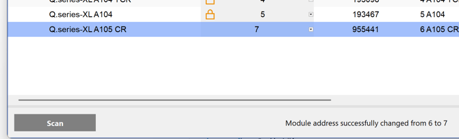
- Once complete you will see the new address and a message that the change was successful.
- Repeat as needed and click Close
- As the configuration to the controller has changed, read the controller into a blank project to automatically perform a controller cleanup.
Setting the module's address with Slave Setup Assistant
-
Download the latest version of Setup Assistant from our website. No license is required to use this software.
-
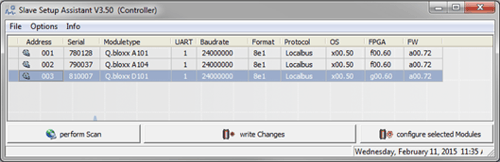
Open Setup Assistant, then select Slave Setup Assistant. The Slave Setup Assistant window will appear. Click the Perform Scan button to search for available controllers on the network.

-
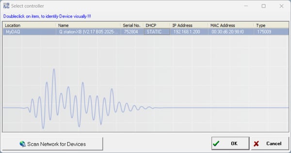
A separate window will appear, showing all connected controllers. Select the controller of interest and click OK.
-
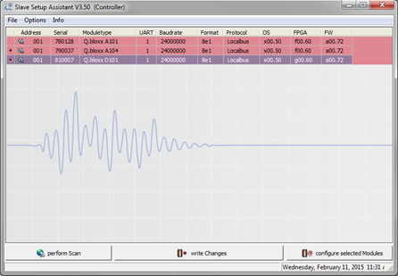
The Setup Assistant will scan all UART ports to detect any connected DAQ modules. All detected modules will be listed.
-
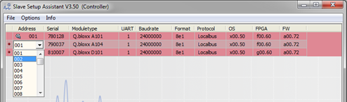
To modify the address of a module, click on the cell under the Address column and enter the new address. Repeat this process for each module as needed.
-
Click the Write changes button to apply the updated settings.