Setting the UART interface
For EtherCAT/XE version of the modules, only UART 1 is utilized. That and the terminating resistor are configured using the DIP switch located inside the Q.series XE module, directly on the CPU board. UART 1 is assigned by having DIP switch 1 + 2 (red) in the ON position. The rest are down except for switches 9+10 (purple) if it is the last module.
The last module on UART 1 must be terminated with a resistor. If a UART is not terminated, reflections may occur on the bus, leading to disturbances or even loss of data transmission.

Example
All modules are set to UART 1. Only the last module (e.g. A116) has pins 9 + 10 ON to activate bus termination.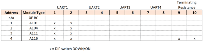
Setting the module's address
Module addresses are set using the DIP switches on the socket/backplane. DIP switch positions 1 through 7 are used to assign module addresses in binary form. Address 0 indicates no fixed hardware configuration.

When configuring module addresses, start with address "1" and assign increasing sequential numbers without gaps.
Location of the address DIP switches on the Q.series X socket:

The 8th switch in the OFF position activates the hot swap feature. When enabled, this stores the module configuration in the socket, allowing for the replacement of faulty modules with others of the same type. Set to ON position to deactivate hot swap.
Example