What Is the missing tooth principle?
The missing tooth principle is a widely used method for measuring rotational speed (RPM) and shaft position. A sensor detects the teeth of a rotating gear, encoder wheel, or trigger wheel and generates a pulse for each tooth that passes.
One or more teeth are intentionally removed to create a reference gap. This larger gap serves as a unique position marker, enabling the measurement system to identify a specific angular position, such as Top Dead Center (TDC) or the start of a revolution.
The missing tooth pattern is commonly used in automotive engines, aerospace turbines and industrial machinery. While the reference gap provides accurate position information, it also creates a longer pulse interval that can affect RPM and frequency calculations if not properly compensated for by the measurement system.
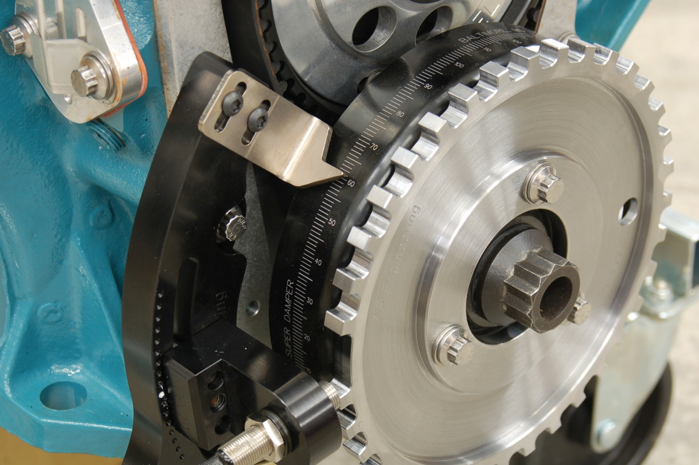 Typical gear tooth sensor with missing teeth
Missing tooth correction for RPM measurement
The Q.series X D107 digital input module supports reference gap correction for accurate RPM, frequency, and counter measurements in missing tooth applications. When reference gap correction is enabled, the module automatically compensates for the missing tooth interval and excludes the reference gap from measurement calculations.
This ensures reliable rotational speed measurement, even when a toothed wheel, gear, or encoder disk includes one or more missing teeth for position referencing.
How reference gap correction works
The reference gap correction algorithm analyses three consecutive measurement periods to detect the missing tooth interval. It identifies the longest period and compares it with the sum of the two shorter periods.
If the longest period is greater than the sum of the two shorter periods, and the reference gap is detected within these three periods, the algorithm adds the configured number of missing edges to the total measured edge count.
The reference gap itself does not generate an additional frequency result when it occurs within the frequency measurement time window. This prevents false RPM or frequency values caused by the longer missing tooth interval.
The Q.series X D107 can correct for up to 15 missing pulses or teeth, making it suitable for demanding rotational speed and position measurement applications.
The reference gap correction algorithm requires a minimum of two consecutive missing pulses (teeth) to detect and compensate for a reference gap. Therefore, configurations with only one missing tooth cannot be corrected by the algorithm.
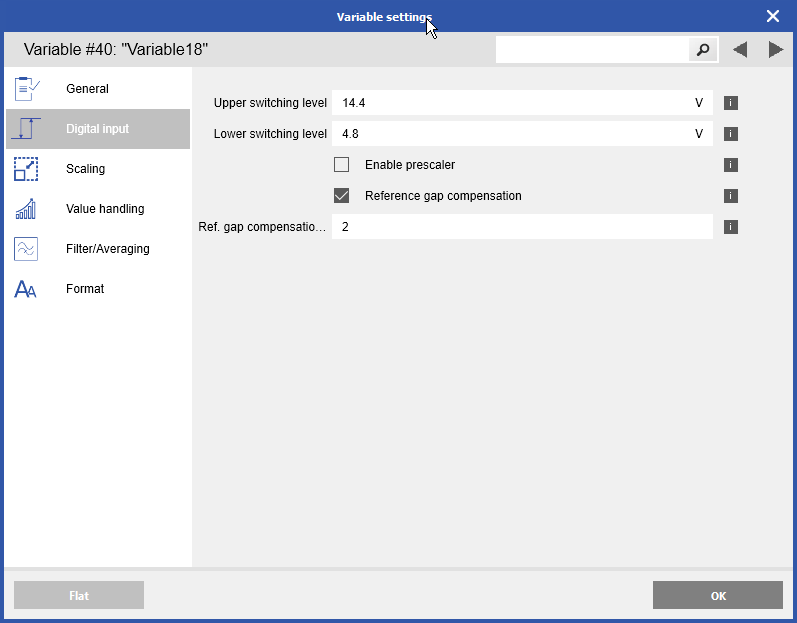
Configuring reference gap compensation in GI.bench
Reference gap compensation can be easily configured in GI.bench using the D107 frequency measurement variable settings. Simply enable the Reference Gap Compensation option and specify the number of missing pulses (teeth) in the encoder wheel or gear.
The D107 module will then automatically compensate for the missing tooth gap during RPM, frequency, and counter measurements, ensuring accurate rotational speed calculations and eliminating errors caused by the reference gap.
The reference gap correction algorithm requires a minimum of two consecutive missing pulses (teeth) to reliably detect and compensate for the gap. Configurations with only one missing tooth cannot be corrected using this method.