![favicon_GI.png]](https://knowledge.gantner-instruments.com/hs-fs/hubfs/favicon_GI.png?width=40&height=40&name=favicon_GI.png)
A Micro-Measurements crack propagation gage measures surface crack growth through resistance changes as parallel resistor strands break. Connect the gage to a Gantner Q.series A105 using a 2-wire resistance measurement and 400 Ω range. Each fractured strand increases resistance, allowing the DAQ system to detect and monitor progressive crack growth.
How a Crack Propagation Gage Measures Crack Growth
The Micro-Measurement Crack Propagation Gages (CPG) consist of multiple parallel resistor strands. These strands, when broken, indicate the rate of crack progression or propagation. When bonded to a structure, the progression of a surface crack through the gage pattern causes successive open-circuiting of the strands, resulting in an overall increase in total resistance. Please refer to the sensor datasheet for more information.
How to Choose Between CPA, CPB, and CPC Crack Propagation Gages
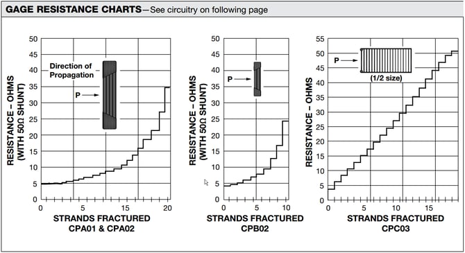
CPA, CPB, and CPC crack propagation gages use multiple parallel conductive strands positioned across the expected crack path. As a surface crack advances through the sensing grid, individual strands break sequentially, producing measurable changes in electrical resistance. The number of strands, strand spacing, grid dimensions, and resistance characteristics determine how crack progression is detected.
|
Gage type |
General characteristic |
Engineering consideration |
|---|---|---|
|
CPA |
Multiple closely spaced parallel strands |
Well suited to monitoring progressive crack growth where relatively fine crack-position increments are required. |
|
CPB |
Fewer sensing strands and a compact measurement pattern |
Useful when the expected crack propagation region or available installation area is limited. |
|
CPC |
Designed for more uniform resistance changes as successive strands break |
Useful when consistent resistance increments can simplify detection and interpretation of crack progression. |
How Does Strand Spacing Affect Crack Growth Measurement?
Strand spacing determines the physical increment of crack propagation represented when the crack reaches successive sensing strands. Smaller spacing provides finer spatial increments, while larger spacing can cover a greater crack propagation distance. The appropriate spacing therefore depends on the expected crack path, required spatial resolution, and available sensor installation area.
How Do Resistance Changes Indicate Crack Propagation?
The measurement system detects crack progression by monitoring the resistance of the crack propagation gage. Each broken strand changes the electrical resistance of the sensing grid. These discrete resistance changes can be recorded by a data acquisition system and correlated with successive stages of crack growth.
When selecting a CPA, CPB, or CPC pattern, engineers should consider the expected crack path, required crack-growth resolution, sensing-grid dimensions, number of strands, strand spacing, and electrical resistance characteristics. Always verify the selected pattern against the manufacturer's current datasheet and the requirements of the specific test or monitoring application.
How to Measure Crack Propagation Gage Resistance with the Q.series X A105
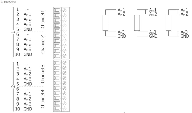
A CPG can be directly connected to the Q.series X A105 using a 2-wire connection and an input range of 400 Ω. As only the relative change of resistance is crucial with a CPG, a 3- or 4-wire connection for accurate absolute resistance measurement is not required.
Taking the CPA-type gage as an example, the total resistance of a gage is around 120 Ohms, which falls within the input range of an A105 (400 Ω). If all 20 strands are undamaged, the gage provides a resistance of 5.224 Ω. If one strand is broken and 19 are intact, the resistance increases to 5.469 Ω, resulting in a resistance change of 0.245 Ω. Using a 400 Ω range, the A105 has an accuracy of 0.012 Ω, which is more than sufficient to detect this resistance change.
When using a 2-wire connection to the gage, it is necessary to jumper the open inputs on the module.
Frequently Asked Questions about Crack Propagation Gage Measurement
How does a crack propagation gage measure crack growth?
A crack propagation gage contains parallel resistor strands bonded across the expected crack path. As a surface crack advances through the pattern, successive strands open, increasing the gage's total resistance. Monitoring these resistance steps allows the progression of the crack to be detected.
Can a crack propagation gage be connected directly to a Q.series A105?
Yes. The gage can be connected directly to a Q.series A105 using a 2-wire resistance connection and the 400 Ω input range. When using the 2-wire configuration, the open module inputs must be jumpered.
Why is a 2-wire connection sufficient for crack propagation measurement?
The important measurement is the relative resistance change produced as strands fracture rather than highly accurate absolute resistance. Therefore, the 3- or 4-wire configurations normally used to compensate lead resistance are not required for this application.
Can the Q.series A105 detect one broken strand in a CPA crack propagation gage?
Yes. In Gantner's CPA example, resistance increases from 5.224 Ω to 5.469 Ω when the number of intact strands changes from 20 to 19, a 0.245 Ω change. The stated A105 accuracy on the 400 Ω range is 0.012 Ω, providing sufficient measurement resolution for this change.
What are CPA, CPB and CPC crack propagation gages?
They are Micro-Measurements crack propagation patterns containing parallel resistor strands. CPA has 20 strands and CPB has 10; CPC also has 20 and is designed to provide more uniform resistance increases between successive strand fractures. Different patterns provide different grid dimensions and strand spacing.