Driver
The latest DASYLab driver for Gantner Instruments Ethernet devices can be downloaded from the Gantner Instruments Download Page. The current driver version is V2.0.0.0.
The driver was developed and tested with DASYLab 2016 (Version 14). A separate driver (V1.0.0.8) is also available for DASYLab Versions 11, 12, and 13.
General Information
The driver enables HighSpeedPort data communication between DASYLab and Q.series, and Q.series X controllers, as well as data exchange with GI.bench.

Since DASYLab and the DASYLab driver are 32-bit applications, the 32-bit version of GI.bench must also be installed and used.
System Requirements
The following files are required for operation:
-
GInsDasyLab.dll (DASYLab plugin)
-
giutility.dll (provides HighSpeedPort communication and device scanning; installed with GI.bench)
Ensure that the required DLL files are located either in the DASYLab installation directory or in C:\Windows\System32.
Network Requirements
For Ethernet communication, the following ports must be available:
-
TCP Port 8001 – HighSpeedPort communication (must be forwarded through any firewall if applicable)
-
UDP Port 5565 – Device discovery via UDP broadcast (module scan)
Installing the DASYLab Driver
To use the Gantner Instruments driver with DASYLab, complete the following steps.
1. Copy the Required DLL Files
Copy the following files to the DASYLab installation directory:
- GInsDasyLab.dll
- GInsDasyLab.chm
- giutility.dll (32-bit version)
2. Register the Driver in DASYLab
Add the driver to the DASYLab.ini file.
For Windows 7 to Windows 10, the file is typically located at:
C:\Users\Public\Documents\DASYLab\14.0.1\ger\DASYLab.ini
Open the file and locate the [Extend] section. Add the following entry:
[Extend]DLL1=GInsDasyLab.dllDLL2=DLAB_UX2.DLLDLL3=DLAB_UX3.DLLDLL4=DLAB_UX4.DLLDLL5=DLAB_UX5.DLLDLL6=DLAB_UX6.DLLDLL7=DLAB_UX7.DLLDLL8=DLAB_UX8.DLL
Save the DASYLab.ini file. The driver will be loaded automatically the next time DASYLab is started.
Verification
After installation:
-
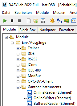
The Gantner Instruments modules are available under Module → I/O.
-
A dedicated TimeBase for the BufferReader module is registered and available for use.

HighSpeedPort TCP/IP
This is the Gantner Instruments-specific binary protocol for fast data transfer over Ethernet. The following types of data communication are possible:
Online (Read/Write) Communication
Each read or write channel configured in DASYLab generates a separate Ethernet communication. Therefore, depending on the number of configured channels, high update rates should be avoided for online communication. For performance reasons, a DASYLab sample rate of approximately 50 Hz is recommended.
Typical applications include:
-
Monitoring of slowly changing values
-
Low-speed control applications
-
Controlling switches, relays, and other digital outputs
-
Executing tare commands on input channels
-
Similar low-bandwidth monitoring and control tasks
For high-speed data acquisition, use the HighSpeedPort interface instead of individual online read/write channels.
Buffered Communication (Read-Only)
The controller can be configured with circular buffers (up to 4 on Q.station). Local data buffers from GI.bench or third-party software using the GInsData API can also be accessed in DASYLab.
Circular buffers are filled with data frames according to the configured synchronisation sample rate in test.commander / GI.bench.
When communicating directly with a device buffer, the controller sends the complete buffer with each data request. The request interval between the host PC and the device is defined by the Comm. Delay (ms) parameter of the function block. Slow request intervals of approximately 200 to 500 ms are recommended.
Recommended for:
-
-
Monitoring highly dynamic values
-
Recording data with an exact FPGA-controlled sample interval
-
Configuration
After installation, the Gantner Instruments modules are available under Module → I/O. In addition, a dedicated TimeBase is registered for the BufferReader module.
The configuration of a Gantner Instruments data acquisition system cannot be performed from within DASYLab. To modify the system configuration, including the hardware structure and sampling rates, use test.commander or GI.bench.
Changing the DASYLab sample rate does not affect the sampling rate of the Gantner DAQ system. The acquisition rate is defined independently within the Gantner system configuration.
Only buffered modules use this TimeBase. All other modules operate using the standard DASYLab TimeBase. The sample rate of the buffered modules cannot be modified within DASYLab, as it is fixed by the configured system synchronisation sample rate of the Gantner DAQ system. A detailed description of the plugin and its modules is available in the module help documentation.
Function Blocks
3 function blocks are available:
-
Online Writer
-
Online Reader
-
Buffer Reader
Take care that the execution of the function blocks depends on the calls of DASYLab, which is a non-real-time application.
Global Control
The Global Control settings of each function block define the behaviour of the driver's Ethernet communication and are used to configure how data is exchanged between DASYLab and the Gantner Instruments system.
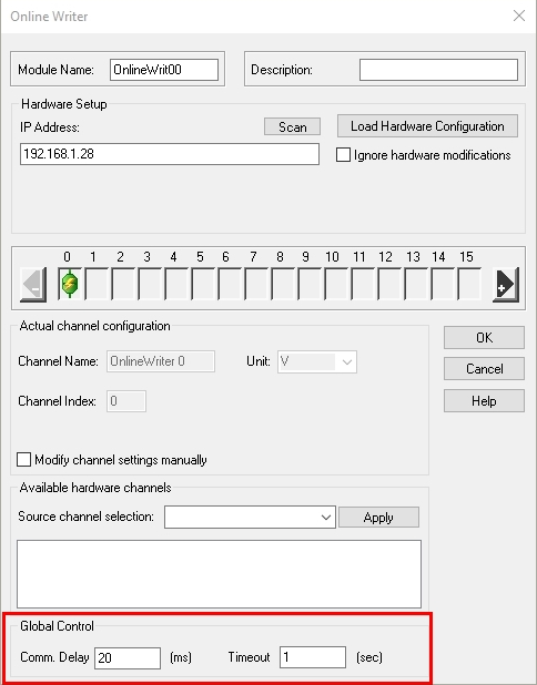
Communication Delay
For Online Read/Write modules, this parameter has no effect. The communication rate is determined by the DASYLab sample rate.
For Buffer Communication, the Communication Delay defines how frequently the driver requests data from the controller. The timing is not deterministic and should be considered an approximate polling interval.
Recommended values:
-
Buffer Reader: 200–500 ms
The communication delay should be selected as a compromise between data refresh rate and controller performance:
-
If the delay is too high, the displayed data becomes less responsive.
-
If the delay is too low, the communication load may negatively affect controller performance.
The controller's System Health should remain above 70%. This can be monitored by creating a virtual variable and using the SystemPerformance() arithmetic function.
Timeout
The Timeout parameter defines the connection and communication timeout of the TCP/IP socket. Increase this value when operating over slow Ethernet connections, VPN connections, or internet-based networks to prevent communication timeouts.
Monitoring Buffer Usage and Configuring Block Size
To verify correct buffer communication and prevent buffer overruns, especially at high data rates, it is recommended to monitor the controller's buffer fill level during operation.
Create a virtual variable in the controller using the arithmetic function:
BufferSize(<bufferindex>)
This function returns the current buffer fill level as a percentage and can be monitored in DASYLab.
Block Size
The Block Size parameter is configured in the Gantner Time TimeBase settings within DASYLab.
Note: The Sample Rate setting in the Gantner Time TimeBase has no effect on the driver.
The Block Size defines how many data frames are transferred from the Gantner driver to DASYLab during each transfer cycle.
- Block Size = 1 means that DASYLab reads one data frame per cycle.
- For high acquisition rates, this may be insufficient if the effective DASYLab processing rate is lower than the controller sample rate.
- As a result, the driver's internal buffer may fill up, preventing new data from being transferred from the controller and eventually causing a controller buffer overrun.
This condition can be detected by monitoring the BufferSize() variable. The value indicates the current fill level of the controller buffer in percent.
Example
-
Controller buffer sample rate: 5000 Hz
-
Block Size: 1
In this configuration, DASYLab may not be able to process incoming data quickly enough, causing the buffer fill level to increase continuously.
To avoid this, increase the Block Size so that DASYLab can transfer and process all incoming data. As a guideline, the buffer fill level should remain well below capacity, for example below 2% during normal operation.
Using the same example:
- Controller sample rate: 5000 Hz
- Block Size: 500
In this case, DASYLab transfers blocks of 500 frames from the driver buffer, corresponding to an effective transfer rate of approximately 10 Hz between the driver and DASYLab. This allows all data to be transferred without causing a controller buffer overrun.
DASYLab 2022 example
Driver Installation
2 steps are necessary to attach the driver to DASYLab:
- Copy DLLs
The following files have to be copied to the installation path of DASYLab:
- GInsDasyLab.dll
- GInsDasyLab.chm
- giutility.dll (32-bit)
- Register Plugin
The driver name needs to be added to the DASYLab.ini file
Windows 7 -> 10:
C:\Users\Public\Documents\DASYLab\14.0.1\ger\DASYLab.ini
In this .ini file there is a section [Extend], where the driver name has to be added:
[Extend]
DLL1=GInsDasyLab.dll
DLL2=DLAB_UX2.DLL #< not used
DLL3=DLAB_UX3.DLL
DLL4=DLAB_UX4.DLL
DLL5=DLAB_UX5.DLL
DLL6=DLAB_UX6.DLL
DLL7=DLAB_UX7.DLL
DLL8=DLAB_UX8.DLL
After storing DASYLab.ini, the driver will be loaded at the next start.
After installation, the Gantner-Instruments modules can be found at "Module -> I/O".
Also, a new TimeBase is registered for the BufferReader module.
IMPORTANT:
Only buffered modules use this time base, online modules run with the DASYLab time base.
The SampleRate cannot be modified because it is fixed to the system sync. sample rate.
First Steps
build a basic project with a Buffered Read block from the Gantner IOs
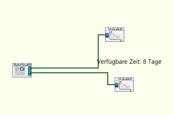
Check the timebases for the Block Size in Gantner Time
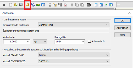
And the Samplerate in DASYLab

The Samplerate in Gantner Time is irrelevant. Data is requested with the Samplerate from DASYLab.
This results in "Gantner Block Size" * "DASYLab Samplerate" = acquirable sample rate
The acquirable sample rate should be at least a bit higher than the actual sample rate of your Gantner system. Otherwise, there will be data loss and non-equidistant data.
Known Issues
V2.0.0.0
-
Changing channel configuration (adding/removing channels via test.commander) → DASY-Lab project needs to be re-loaded (local process buffer must be reinitialized)
-
Online communication: each channel (read or write) causes a separate communication → it is recommended to use only “slow” rates < 50 Hz to avoid high load on the controller.
V1.0.0.8
-
The DasyLab driver cannot handle variable names with more than 19 characters. Take care of this in your test.commander configuration!
-
When adding/deleting channels in test.commander, the Gantner Instruments function blocks in your DASYLab project need to be updated. → Re-Load Hardware Configuration!
-
Drag and drop of display elements in DASYLab may cause DASYLab not to run smoothly (DASYLab is a none-real-time application) → this can lead to a problem with Online Read/Write function blocks, which are only executed when called by DasyLab (no buffered read/write → only 1 value at each call)
-
Writing on USINT16 or SINT16 variables does not work correctly (for example set value = 1 → channel value = 257) when using eGateHighSpeedPort.DLL V2.0.1.9., which is included in the driver setup. Using the newer version V2.0.2.1, this problem is solved.