![favicon_GI.png]](https://knowledge.gantner-instruments.com/hs-fs/hubfs/favicon_GI.png?width=40&height=40&name=favicon_GI.png)
An open-drain output can connect to a Gantner D101 digital input when an appropriate pull-up resistor establishes the HIGH state. Select the resistor using the supply voltage, D101 logic thresholds and input limits, and the output device’s sink-current capability. A 24 V supply with 2.5 kΩ draws approximately 9.6 mA.
What Is an Open-Drain Output?
An open-drain output is a digital output that can perform two actions:
- Pull the signal to ground when switched on
- Disconnect from the signal when switched off
It cannot actively drive the signal high. Therefore, an external pull-up resistor or load connected to a positive supply voltage is required.
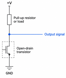
When the transistor is on, the output is low. When it is off, the pull-up makes the output high. This is also called a sinking output and is commonly used for alarms, switching relays, level adaptation and shared digital signal lines.
How to Connect an Open-Drain Output to a Gantner D101 Digital Input
The following connection information applies when connecting an open-drain digital output to a D101 digital input (datasheet).
Check D101 Input Voltage, Logic Levels, Current, and Grounding
Before connecting an open-drain output to the D101, verify that the signal voltage and current are compatible with the D101 digital input specifications. Check the permitted input voltage range, logic thresholds, supply voltage, and maximum input ratings in the applicable Gantner Instruments hardware documentation. The pull-up resistor must be selected to provide a reliable HIGH state while limiting the current when the open-drain output switches LOW. Also confirm whether a common ground is required between the output device and the D101, and verify the expected ON/OFF logic states before commissioning. Always use the specified electrical limits for the D101 rather than assuming standard digital I/O levels.
Open-Drain to D101 Wiring Diagram
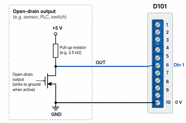
How to Select a Pull-Up Resistor for a D101 Open-Drain Input
The Q.bloxx XL D101 supports selectable TTL and 24 VDC digital-input logic, with a 30 VDC maximum input voltage and 2 mA maximum input current. These limits, along with the logic thresholds and open-drain sink-current capability, must be considered when selecting a pull-up resistor.
24 VDC and 2.5 kΩ Pull-Up Resistor Example
An open-drain output requires a pull-up resistor to establish a defined HIGH state when the output is OFF and limit current when it pulls the signal LOW.
With a 24 VDC supply and 2.5 kΩ pull-up resistor:
I = V / R = 24 V / 2500 Ω = 9.6 mA
When the output is ON, approximately 9.6 mA flows through the pull-up resistor, so the open-drain device must be able to sink this current. This is not the same as the current into the D101 input, which must remain within its specified 2 mA maximum.
When the output is OFF, the resistor pulls the signal toward 24 VDC, creating the HIGH state.
-
Output ON: toward 0 V → LOW
-
Output OFF: toward 24 VDC → HIGH
-
Pull-up resistor: 2.5 kΩ
-
Pull-up current when LOW: ≈ 9.6 mA
-
D101 limits: 30 VDC maximum input, 2 mA maximum input current
How to Verify the Pull-Up Resistor Value
Before selecting the final resistor value, verify that:
-
The HIGH and LOW voltages meet the D101 logic thresholds.
-
The D101 input remains below 30 VDC and 2 mA.
-
The open-drain device can safely sink the pull-up current.
-
The resistor has sufficient power rating.
For 24 VDC and 2.5 kΩ:
P = V² / R = 24² / 2500 ≈ 0.23 W
Select a resistor with sufficient power margin.
2.5 kΩ is an example, not a universal D101 pull-up value. Always verify the resistor against the D101 input specifications and the open-drain device ratings
Frequently Asked Questions About Connecting an Open-Drain Output
Can an open-drain output be connected directly to a Gantner D101 digital input?
An open-drain output requires a pull-up resistor or suitable load to create the HIGH state. Verify that the pull-up voltage, resistance, D101 logic thresholds, current limits, and grounding are compatible with the connected device.
What pull-up resistor should I use with a D101?
There is no universal value. The resistor must produce a voltage above the configured D101 HIGH threshold while keeping the LOW-state sink current within the output device's rating. The article's 2.5 kΩ at 24 VDC example produces approximately 9.6 mA.
What are the D101 digital input logic levels?
For the Q.bloxx XL D101, TTL logic is specified as below 0.8 VDC for LOW and above 3 VDC for HIGH. With 24 VDC/HTL logic, −3 to 5 VDC is LOW and 11 to 30 VDC is HIGH.
Why does an open-drain output need a pull-up resistor?
An open-drain output can pull a signal LOW but cannot actively drive it HIGH. The pull-up resistor establishes the HIGH voltage when the transistor is off while limiting current when the transistor switches on.
Is an open-drain output the same as an NPN or sinking output?
These terms are often used together because an NPN/open-drain output typically sinks current by switching the signal toward ground. Engineers should still verify the actual output circuit and electrical specifications of the connected device before wiring it to the D101.