![favicon_GI.png]](https://knowledge.gantner-instruments.com/hs-fs/hubfs/favicon_GI.png?width=40&height=40&name=favicon_GI.png)
A loop-powered sensor uses the same two-wire circuit for electrical power and its measurement signal, typically 4–20 mA. To connect one to a Gantner Instruments DAQ module, wire the sensor, power supply and analog current input in series, observing the correct AI+ and AI− connections for the selected wiring method.
What Is a Loop-Powered 4–20 mA Sensor?
Loop-powered sensors are field sensors powered directly by the same electrical current loop used to transmit the measurement signal, most commonly a 4–20 mA current loop.
A typical current loop consists of a transmitter (sensor), receiver, and power supply connected in series. In the example below, the sensor acts as the transmitter and the Gantner Instruments measurement module as the receiver. Both electrical power and the analogue measurement signal are transmitted over the same pair of wires.
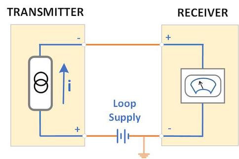
How a 4–20 mA Current Loop Works
A 4–20 mA current loop is commonly used to transmit sensor measurements in industrial data acquisition and monitoring systems. In a typical 2-wire loop-powered sensor, the same two wires provide power to the transmitter and carry the measurement signal.
The loop consists of three main components connected in series: a DC loop power supply, a 2-wire sensor or transmitter, and the DAQ analog current input. Because these components form a single series circuit, the same current flows through the transmitter and the DAQ input.
The transmitter regulates the loop current according to the measured physical quantity. Typically, 4 mA represents the lower end of the measurement range and 20 mA represents the upper end. For example, a pressure transmitter configured for 0–10 bar would normally output 4 mA at 0 bar and 20 mA at 10 bar.
Typical current path:
DC loop supply (+) → 2-wire transmitter → DAQ current input → DC loop supply (−)
The DAQ system measures the loop current and converts the 4–20 mA signal into the corresponding engineering value, such as pressure, force, temperature, displacement, or flow.
When connecting a loop-powered sensor, ensure that the power supply provides sufficient voltage for the transmitter and the total voltage drop across the measurement loop. Also observe the correct polarity and input configuration specified for the DAQ module.
How to Wire a Loop-Powered 4–20 mA Sensor to a Gantner DAQ Module
There are two methods for connecting a loop-powered sensor to a Gantner Instruments measurement module. In both configurations, the power supply, sensor transmitter, and receiver module are connected in series, allowing the same loop current to provide sensor power and carry the measurement signal.
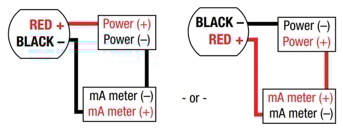
Wiring Method 1: Connect the DAQ Input on the Negative Side of the Current Loop
Connect the loop as follows:
-
Power supply negative (−) → AI− of the measurement channel
-
Sensor negative (−) → AI+ of the measurement channel
Wiring Method 2: Connect the DAQ Input on the Positive Side of the Current Loop
Alternatively, connect the loop as follows:
-
Power supply positive (+) → AI+ of the measurement channel
-
Sensor positive (+) → AI− of the measurement channel
In both methods, the measurement module is connected in series with the current loop.
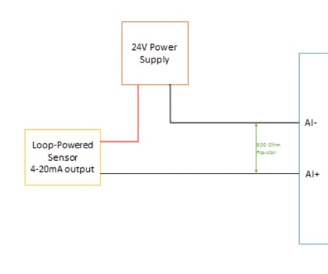
4–20 mA Wiring Example: Q.bloxx A108 with Shunt Resistor Terminal Block
The example below shows the connection to an A108 measurement module using a terminal block with an integrated shunt resistor.
Frequently Asked Questions About Loop-Powered 4–20 mA Sensors
What voltage supply is required for a 2-wire 4–20 mA sensor?
The loop supply must provide sufficient voltage for the sensor or transmitter plus the voltage drops across the DAQ input, shunt resistor, wiring and other series components. Check the sensor and DAQ specifications before selecting the supply voltage. A 24 VDC supply is common, but it should not be assumed for every device.
Why does a 4–20 mA input use a shunt resistor?
A precision shunt resistor converts loop current into a measurable voltage according to Ohm's law. For example, a 250 Ω resistor converts 4–20 mA into 1–5 V. The required resistor depends on the DAQ input and measurement hardware.
What does 4 mA represent in a 4–20 mA current loop?
Typically, 4 mA represents the lower end of the configured measurement range and 20 mA represents full scale. The 4 mA “live zero” also allows the two-wire transmitter to receive operating power while representing a zero process value.
What happens if the polarity of a loop-powered sensor is reversed?
A 2-wire loop-powered transmitter is polarity-sensitive. Incorrect wiring can prevent the loop from operating or produce no valid measurement, so verify the transmitter terminals, loop supply polarity and DAQ AI+/AI− connections before applying power.
What is the difference between a loop-powered 2-wire sensor and an externally powered sensor?
A 2-wire loop-powered sensor receives power through the same conductors carrying its 4–20 mA signal. An externally powered transmitter has separate power connections or its own supply. The distinction matters because the appropriate DAQ wiring configuration depends on the transmitter's output and power arrangement.