![favicon_GI.png]](https://knowledge.gantner-instruments.com/hs-fs/hubfs/favicon_GI.png?width=40&height=40&name=favicon_GI.png)
Carrier frequency strain gauge measurement uses alternating-current bridge excitation and synchronous demodulation to measure small resistance changes while reducing sensitivity to amplifier offset, low-frequency drift and certain types of interference. Gantner Instruments A106 amplifiers support 600 Hz and 4.8 kHz excitation, while the A156 uses 4.8 kHz. Frequency selection depends on measurement bandwidth, sensor configuration and cable characteristics.
How Does Carrier Frequency Strain Gauge Measurement Work?
Conventional strain gauge amplifiers use direct current (DC) excitation to measure small resistance changes in a Wheatstone bridge. Carrier frequency amplifiers instead excite the bridge with an alternating current (AC) voltage, typically at frequencies between 600 Hz and 4.8 kHz. The strain gauge modulates the amplitude of this carrier signal. The amplifier subsequently demodulates and filters the signal to recover the strain measurement.
The main advantages of carrier frequency technology include:
- Low noise and interference rejection: Selective amplification and demodulation reduce sensitivity to unwanted electrical interference.
- Excellent long-term stability: Reduced sensitivity to amplifier offset and low-frequency drift makes the technology suitable for static and long-duration measurements.
- High measurement accuracy: Stable excitation and precise signal conditioning enable reliable detection of small strain variations.
- Sensor versatility: The same technology supports strain gauges and inductive transducers, including Linear Variable Differential Transformers (LVDTs) and Rotary Variable Differential Transformers (RVDTs).
How to Choose a Carrier Frequency Strain Gauge Amplifier
Selecting the appropriate amplifier requires more than comparing measurement accuracy. Several technical characteristics influence overall measurement quality and system flexibility.
Carrier frequency and measurement bandwidth: Higher carrier frequencies generally support faster measurement dynamics and greater separation from low-frequency interference. A 4.8 kHz carrier is therefore preferable for many dynamic applications, while 600 Hz may be sufficient for slower measurements. The actual usable bandwidth also depends on demodulation and filtering.
Carrier frequency and sensor cable length: Higher carrier frequencies generally support greater measurement bandwidth but can increase sensitivity to cable capacitance, particularly with long sensor cables. Cable capacitance can affect the amplitude and phase of the excitation signal, potentially introducing measurement errors. Lower carrier frequencies are therefore often preferable for longer cable runs, while higher frequencies are better suited to applications requiring faster measurement dynamics. Always consider the amplifier's specified maximum sensor cable length when selecting the carrier frequency.
|
Bridge excitation |
DC |
600 HZ CF |
4.8 kHz CF |
|
Dynamic measurement |
⬆️ |
⬇️ |
↗️ |
|
High-resistance sensors |
⬆️ |
⬆️ |
⬇️ |
| Stability & EMC immunity | ⬇️ | ⬆️ | ↗️ |
| Long sensor cables | ⬆️ | ⬆️ | ↘️ |
| Quarter-bridge compatible | ⬆️ | ⬆️ | ↘️ |
| Inductive sensors | ⬇️ | ⬇️ | ⬆️ |
Scalability and synchronisation: Multi-channel systems benefit from synchronised carrier excitation to prevent beat frequencies and interference between measurement channels. Deterministic acquisition synchronisation is equally important when analysing correlated mechanical events.
Excitation voltage: Higher excitation improves signal amplitude but increases strain gauge self-heating. Selectable excitation allows optimisation for different bridge resistances and sensor characteristics.
Channel isolation: Galvanic isolation between individual channels, power supply and communication bus reduces interference and ground-loop problems, particularly in distributed measurement systems.
Integrated signal processing: Configurable filtering, linearisation and mathematical functions reduce external processing requirements and simplify system integration.
Gantner Instruments A106 and A156 Carrier Frequency Amplifiers
Gantner Instruments offers two carrier frequency amplifier families within its modular data acquisition platform.
Q.series X A106
- Two galvanically isolated analogue input channels.
- Selectable 600 Hz or 4.8 kHz carrier frequency, or DC excitation.
- Selectable 2.5 V or 5 V excitation.
- 24-bit conversion and up to 20 kHz sampling per channel.
- Two additional analogue outputs.
Q.series X A156
- Four galvanically isolated analogue input channels.
- Fixed 4.8 kHz carrier frequency.
- Selectable 2.5 V or 5 V RMS excitation.
- 24-bit conversion and up to 20 kHz sampling per channel.
- Multiple measurement ranges, digital filtering and integrated signal conditioning.
Both modules support full-bridge and half-bridge sensors, with quarter-bridge operation requiring an appropriate completion terminal.
Recommended Carrier Frequency Configuration and Synchronisation
Carrier frequency: Use 4.8 kHz as the preferred setting for A106 modules where sensor compatibility permits, particularly for dynamic measurements. Select 600 Hz for static or slowly varying measurements and applications involving longer sensor cables, where reduced sensitivity to cable capacitance is beneficial. The A156 operates exclusively at 4.8 kHz.
Quarter-bridge strain gauge measurement at 4.8 kHz is more sensitive to cable capacitance, which can cause bridge imbalance, phase shifts and measurement errors. A lower carrier frequency of 600 Hz reduces these effects and is therefore preferable for longer sensor cables.
Excitation voltage: Start with 2.5 V to minimise sensor self-heating. Select 5 V when improved signal amplitude is beneficial and the sensor resistance, power rating and thermal conditions permit.
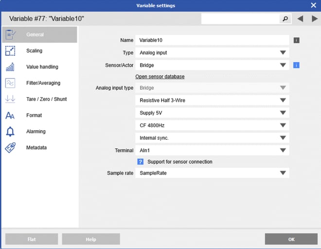
Carrier frequency synchronisation: When using multiple A106 or A156 modules on the same UART, synchronise their carrier frequency generators to prevent crosstalk and beat frequencies in the measurement signals. Three synchronisation modes are available:
- No synchronisation: Suitable when using a single carrier frequency module. All carrier frequency generators within the module are automatically synchronised.
- Internal synchronisation (Master): Configure one A106 module per UART as the master to provide the carrier frequency reference.
- External synchronisation (Slave): Configure all remaining A106 modules to synchronise with the master via the Sync A and Sync B lines of the Q.bloxx socket.
All externally synchronised modules must use the same carrier frequency as the master. Only one master is permitted per UART.
Note: Carrier frequency synchronisation prevents interference between excitation signals and is distinct from measurement channel time synchronisation.
Frequently Asked Questions
What is the difference between carrier frequency and direct-current strain gauge excitation?
Direct-current excitation applies a constant bridge voltage, whereas carrier frequency excitation uses an alternating voltage and synchronous demodulation. Carrier frequency measurement reduces sensitivity to amplifier offset, low-frequency drift and certain types of interference. The most suitable method depends on measurement dynamics, noise conditions and the sensor configuration.
Is 4.8 kHz better than 600 Hz for strain gauge measurements?
A 4.8 kHz carrier generally provides more scope for measuring faster strain variations, depending on the amplifier's demodulation and filtering. A 600 Hz carrier can be advantageous for slowly varying measurements and longer sensor cables because cable capacitance generally has less influence at lower excitation frequencies. Neither frequency is universally better.
Does a 4.8 kHz carrier frequency mean the amplifier can measure strain at 4.8 kHz?
No. The carrier frequency is the alternating-current excitation frequency, not the usable strain measurement bandwidth. The demodulation process and configured filters determine the actual signal bandwidth. The maximum sampling rate is a separate specification and does not establish the usable measurement bandwidth.
Can quarter-bridge strain gauges be measured with 4.8 kHz carrier frequency excitation?
Yes, but quarter-bridge measurements at 4.8 kHz are more sensitive to parasitic cable capacitance, which can introduce bridge imbalance, phase shifts and measurement errors. A lower carrier frequency of 600 Hz reduces these effects and is generally preferable for longer sensor cables.
Why is carrier frequency synchronisation important when using multiple strain gauge modules?
Unsynchronised carrier generators can produce interference or beat frequencies through coupling between sensor supply and measurement circuits. For A106 modules on the same UART, configure one internal synchronisation master and the remaining carrier-frequency inputs for external synchronisation at the same frequency. The exact procedure for mixed A106 and A156 installations should be confirmed against the applicable module documentation.